Assembly
This guide assumes that you’ve unboxed the FF10 and installed CPU, RAM and Storage onto the motherboard.
CPU Cooler
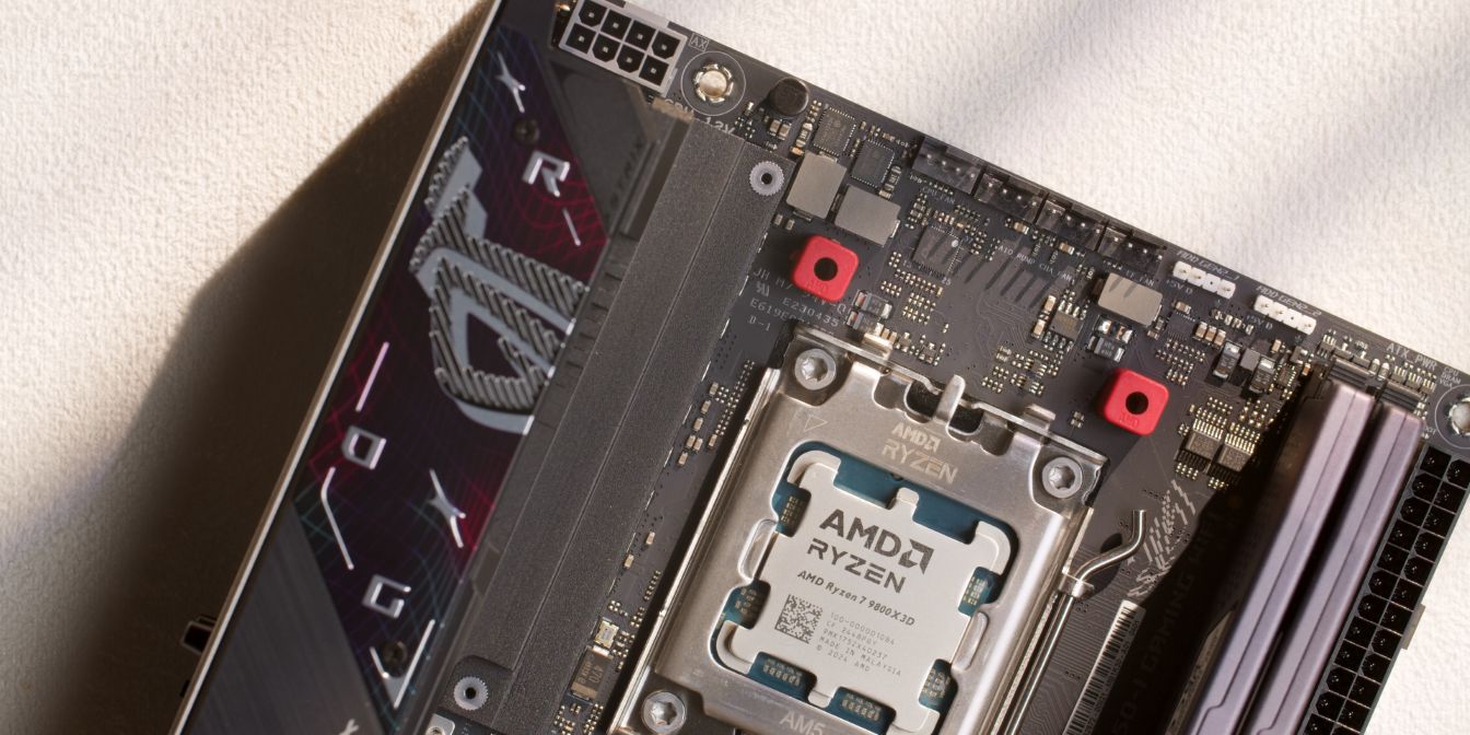
To install the ID Cooling IS-67-XT place the four included plastic standoffs onto the AM5 mounting posts.
Place the AM5 brackets onto the standoffs as shown, then secure them with the four included screws. Tighten until you feel resistance then stop, no need to over-tighten.
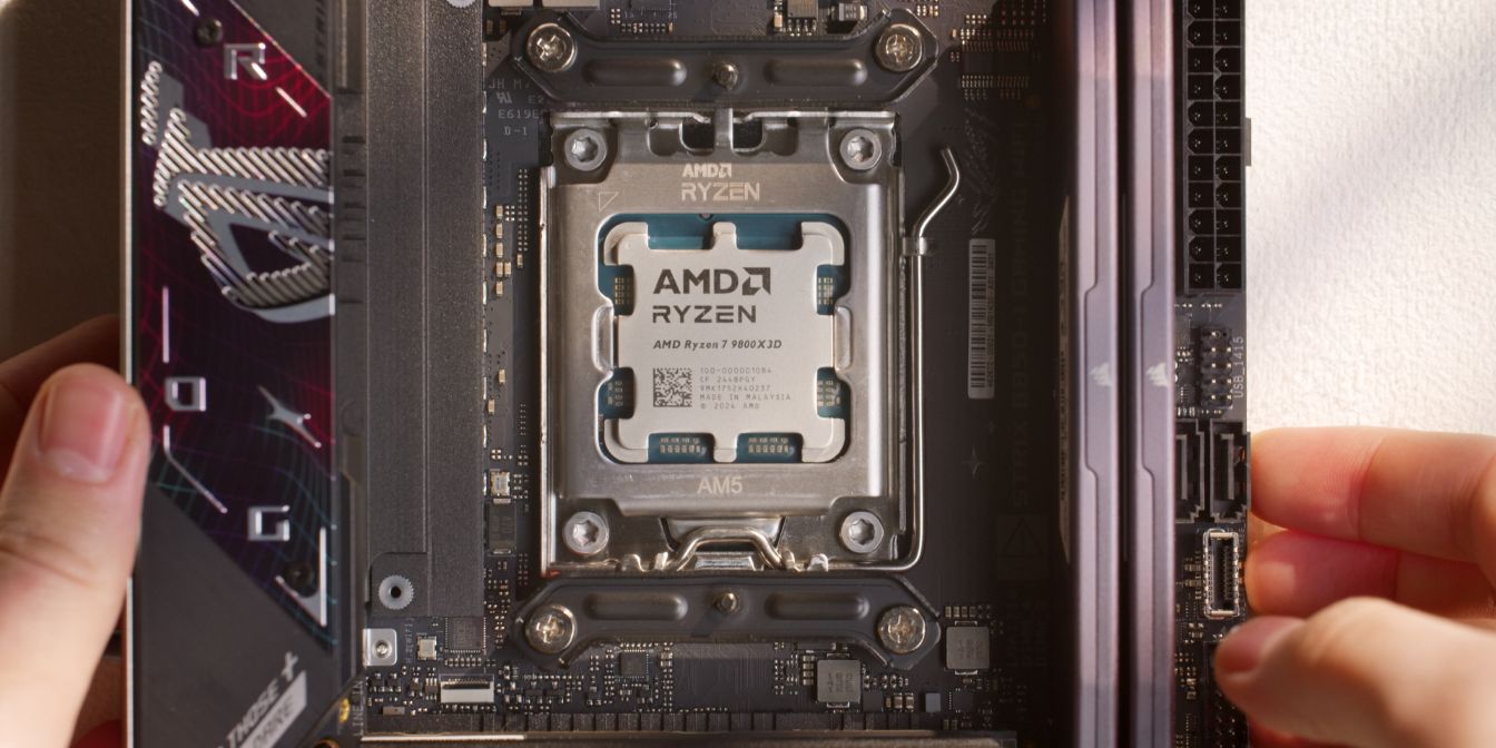
Place the heatsink over the CPU, aligning the captive screws over the threaded posts of the brackets.
Note the “flipped” orientation of the cooler here, with the heatsink overhanging the RAM sticks (right) instead of the motherboard VRM heatsink (left).
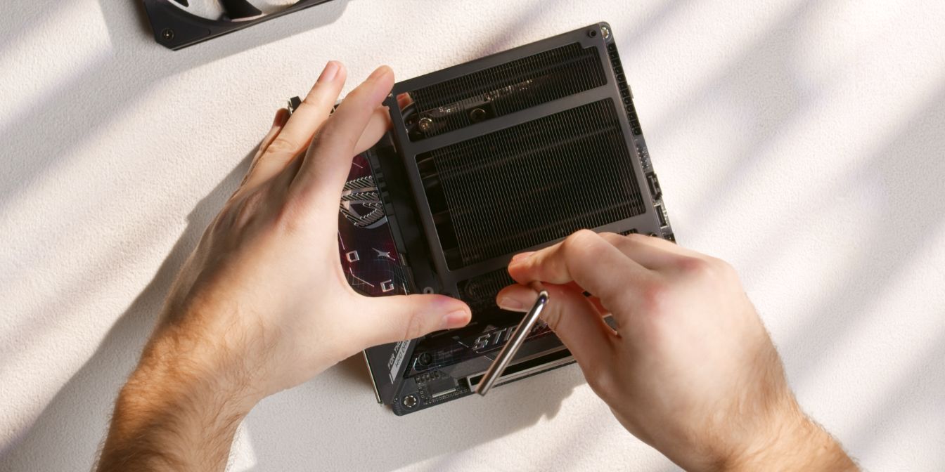
Use the included Philips head Allen key to tighten the screws. Get one of the screws started with one or two turns, then move on to the other and repeat until you feel sudden resistance.
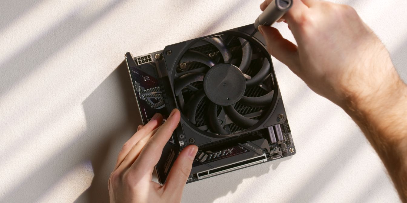
Place the CPU fan onto the heatsink and secure it with four of the included screws intended to be used with 15mm (slim) fans.
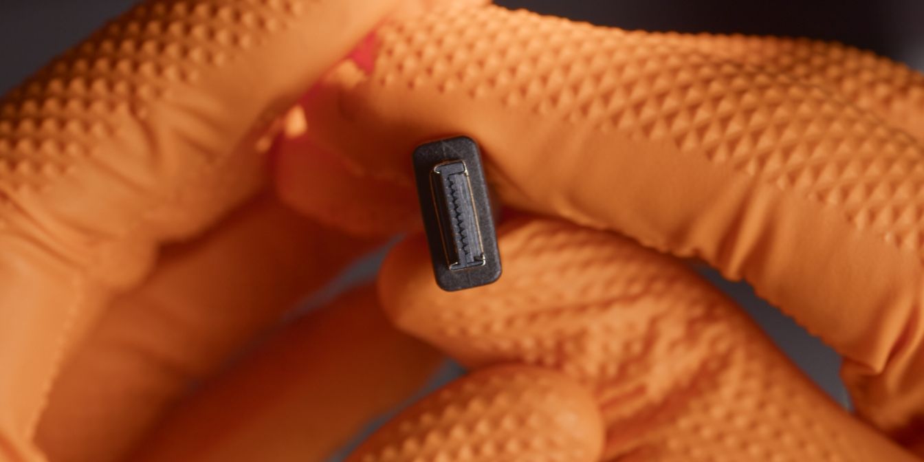
Power cable
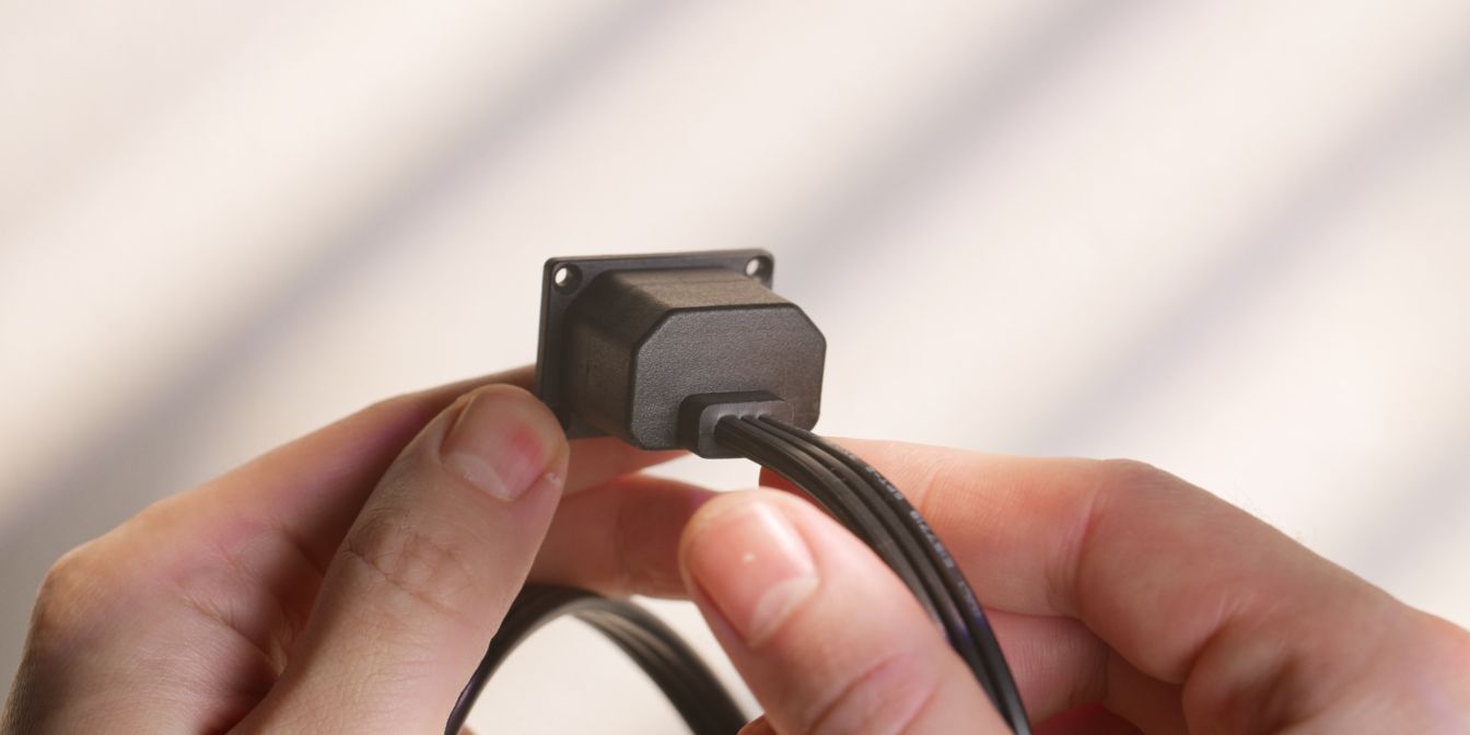
Next, let’s add the custom internal power cord extension cable. This is a custom design with a “low profile” inlet plug that needs to be secured with four M2 screws.
You’ll need a slim screwdriver for this step.
It’s important to get this done now because it will be nearly impossible after we add in the motherboard.
Motherboard
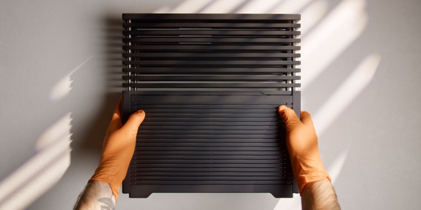
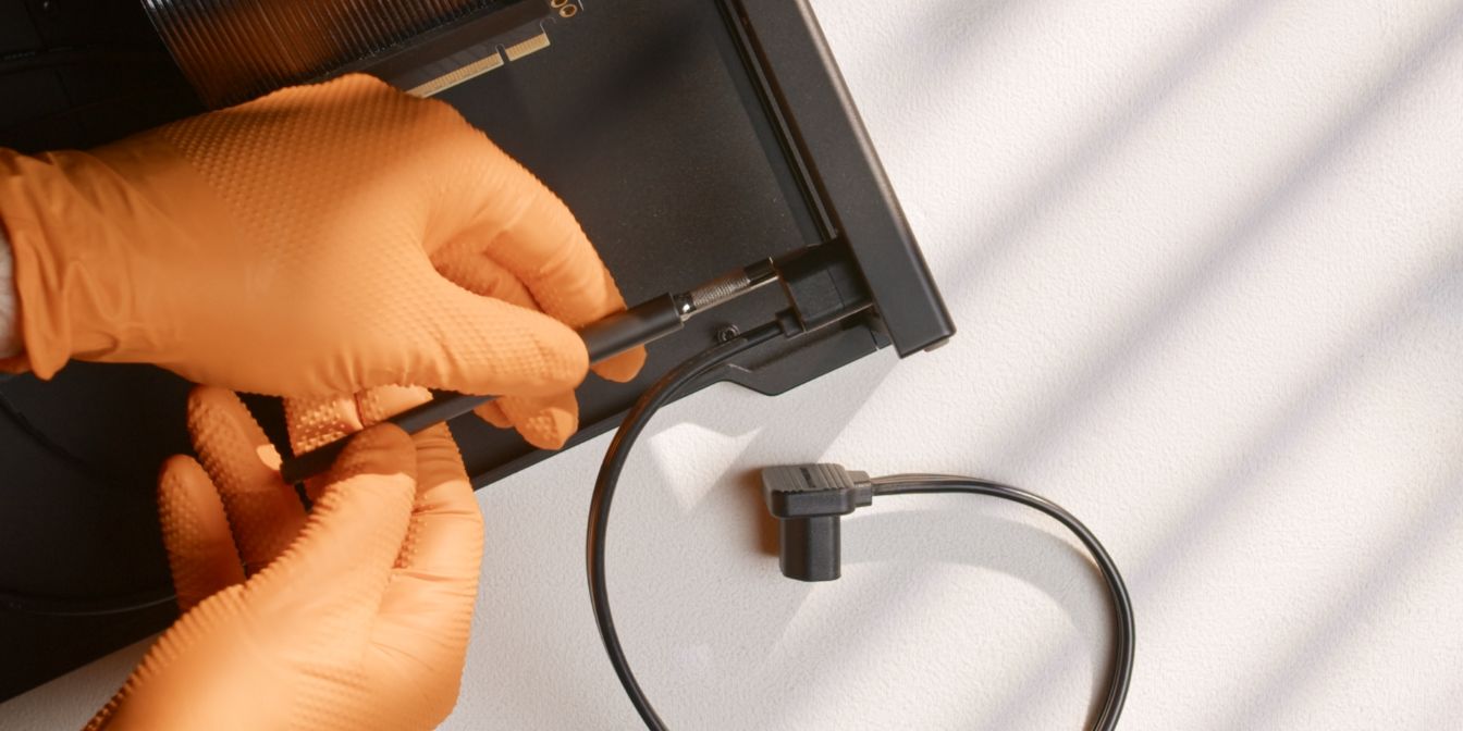
Access the lower compartment of the FF10 by sliding the vented side panel downwards.
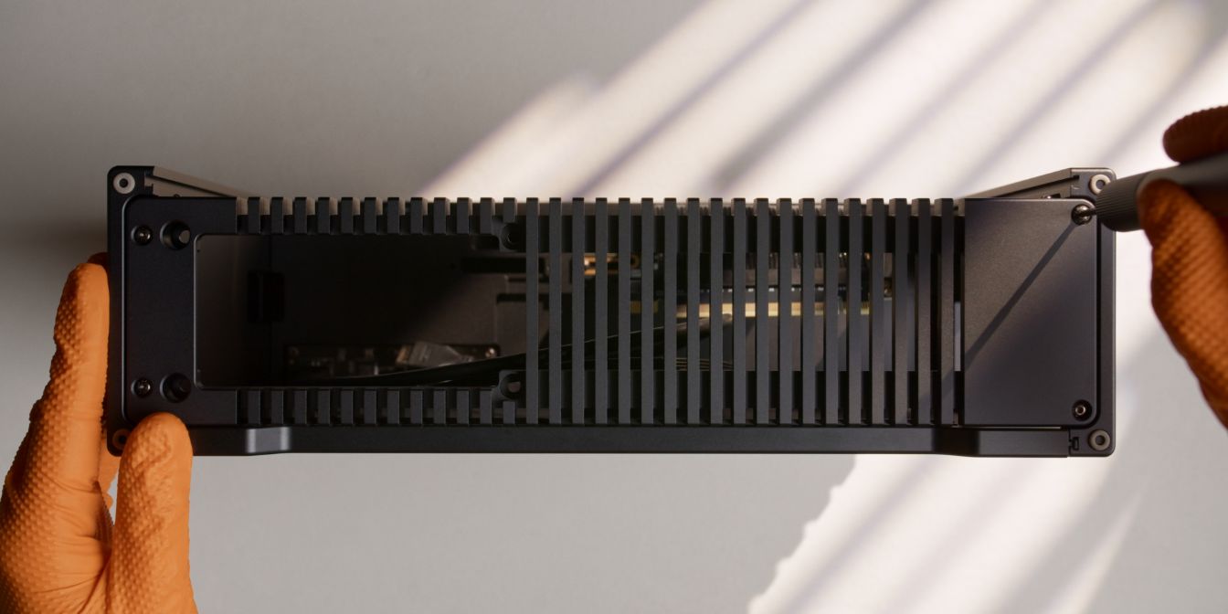
To make it easier to fit the motherboard (and PSU later) we need to also remove the bottom panel of the FF10.
Undo the four screws located in each corner of the panel, then firmly pull it away from case.
Hold the motherboard in position and connect the PCIe Gen5 riser cable, then carefully angle it so that it clears the internal power cable.
Place the motherboard on the standoffs below and secure it with four of the included M3 button head screws.
It might be difficult getting at the screws here so using tweezers to get the screws in position is a nice hack.
Connect the FF10 front panel cables to the motherboard.
There’s just enough room for them to be tucked away neatly underneath the PSU, so use the image above as reference for how to cable manage them.
Be careful when connecting the front panel Type-E plug. This plug is keyed, so do NOT force it in. It should connect with a clear and defined “click” sound.
PSU
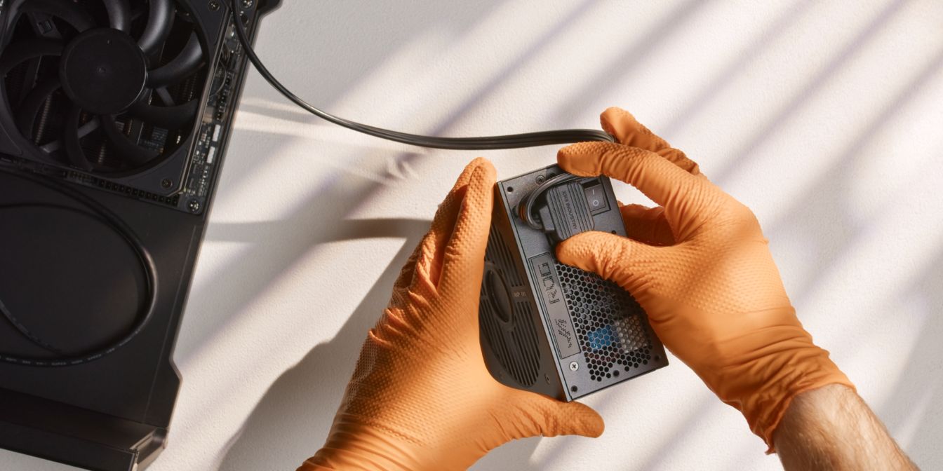
Connect the internal power cable plug to the PSU inlet.
We need to bend the cable quite aggressively here so that it clears the bottom panel cutout.
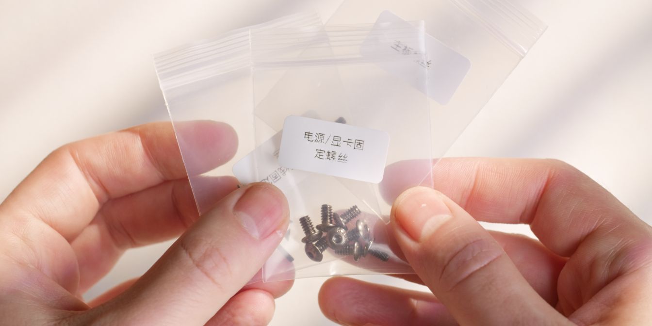
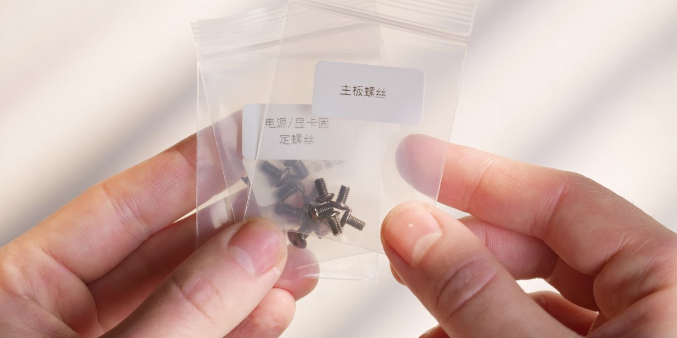
Identify the included PSU screws.
Power supplies use UNC threads instead of metric, so using the correct ones is crucial.
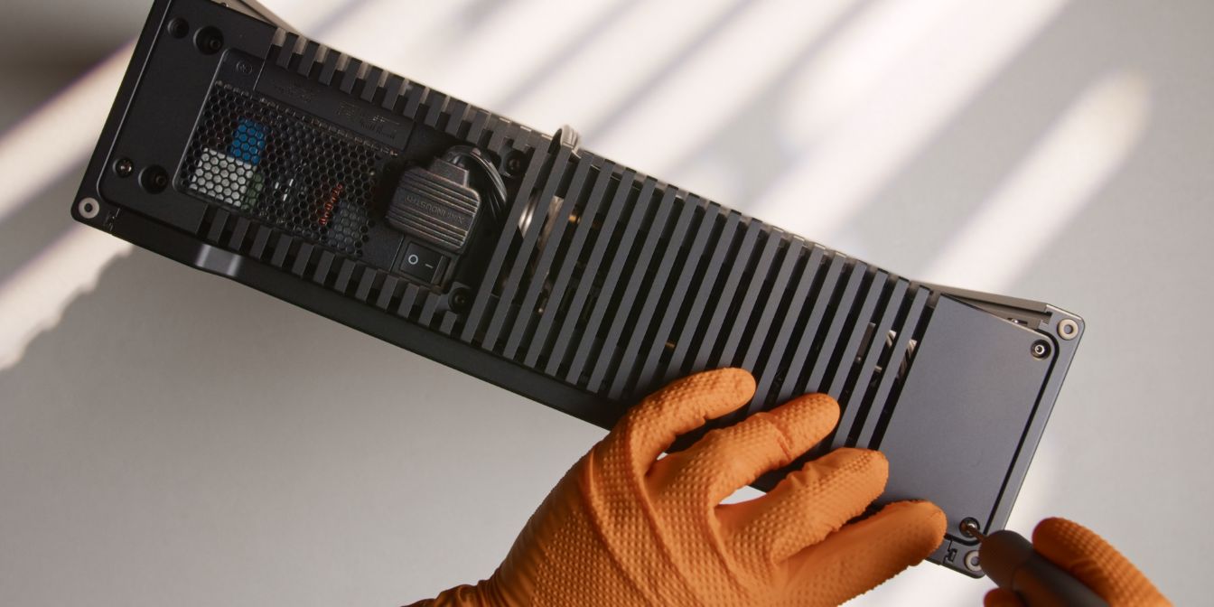
Secure the PSU to the bottom panel with four of the included screws. Tighten until snug, but don’t overtighten.
Make sure the power cable goes through the panel cutout as shown and that it doesn’t protrude away from the panel (towards the case feet).
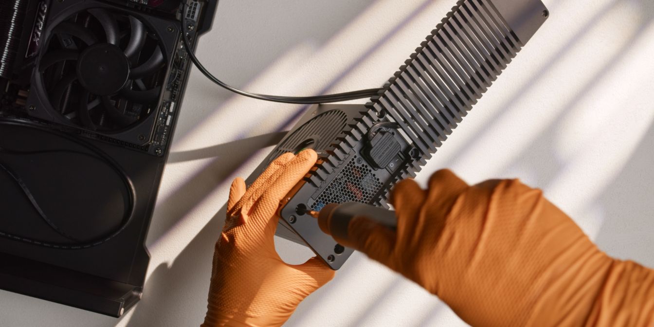
PSU Cables
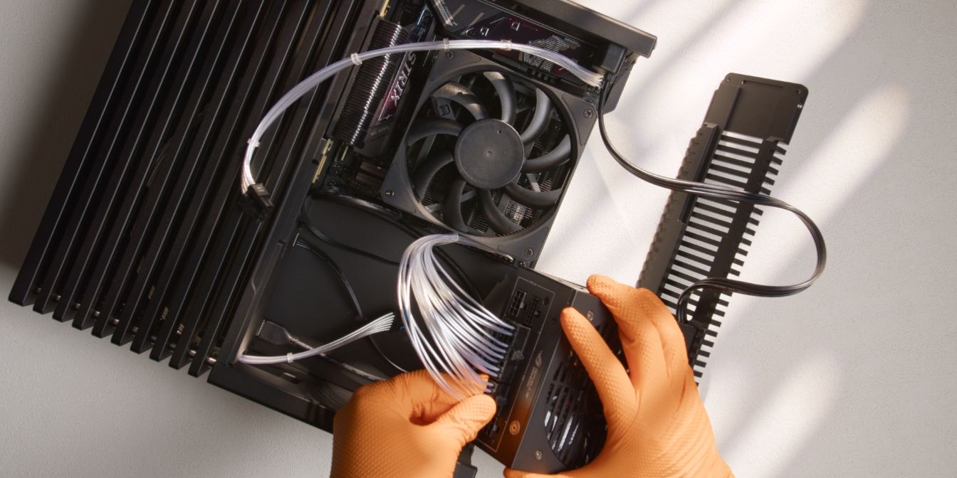
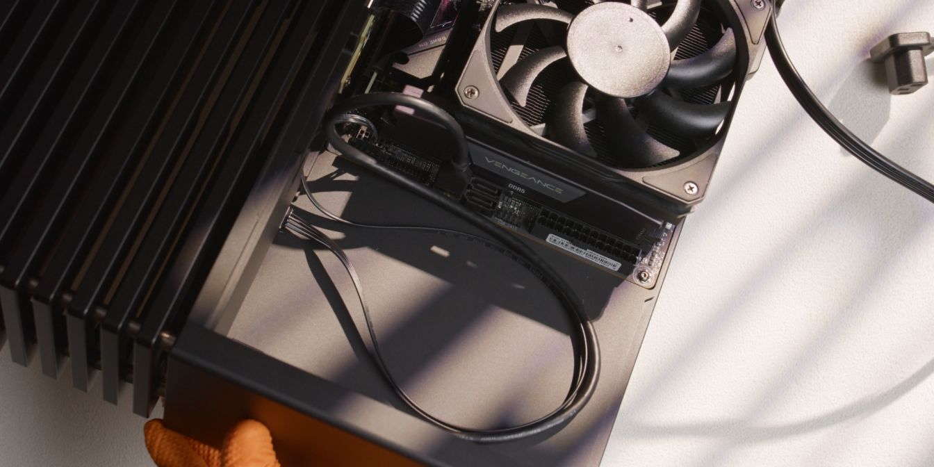
Before adding back the bottom panel we should pre-route the PSU cables.
Route the GPU 12V-2X6 cable through the pass-through cutout in the upper left part of the internal compartment, leaving about 10cm of excess.
Connect the CPU 8 pin cable to the motherboard and route it either as shown or underneath the CPU heatsink (towards the bottom panel), as per your preference.
Connect the ATX 24 pin cable to the motherboard and PSU.
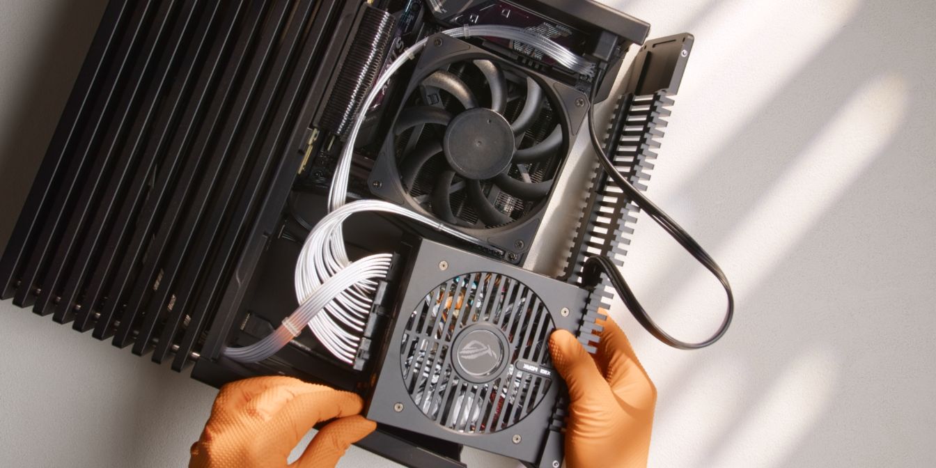
Bring the PSU / bottom panel assembly closer in position and connect the CPU 8 pin and GPU 12V-2x6 cables to the PSU, listening for the audible “click” of the retention latches.
Place the PSU in position, sitting “on top” of the front panel cables added earlier.
Finally, tuck the PSU power cable excess in between the PSU and motherboard.
Secure the bottom panel back in place.
Make sure none of the cables are “catching” or preventing the bottom panel from sitting flush.
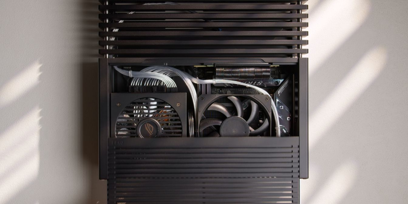
Place the side panel back on the case.
If the PCIe Gen5 riser is touching the panel as it slides back into position, try to gently increase its bend radius so that it no longer interferes with the panel.
GPU
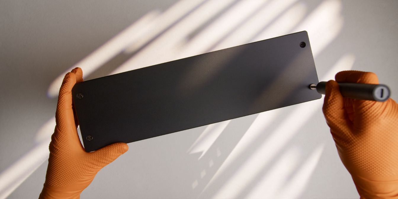
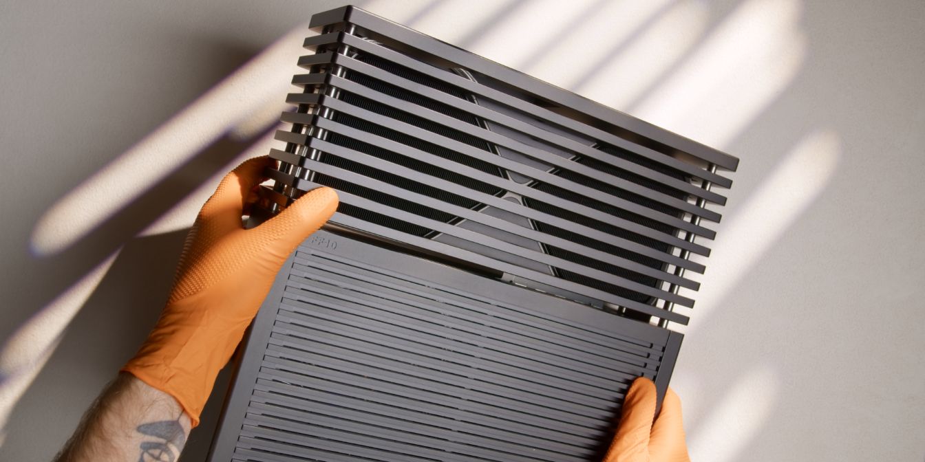
To get the GPU inside the FF10 we need to first remove the top plate. You’ll need to use an H2.5 screwdriver bit to undo the four screws holding it in place.
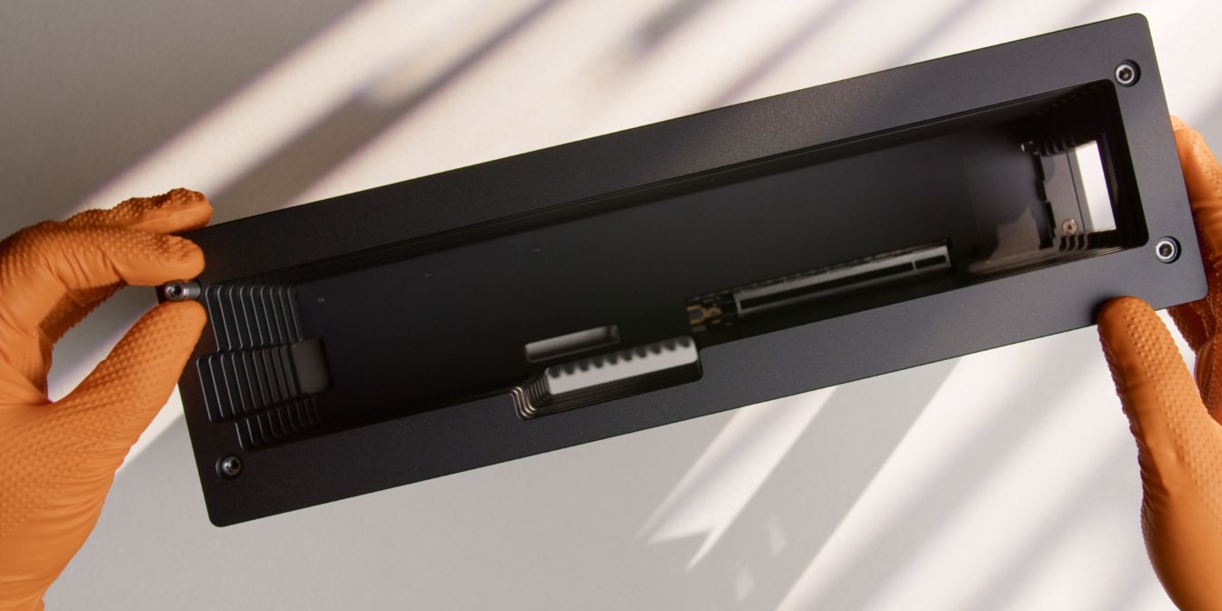
We’ll need to remove two more plates.
Each plate is stacked on top of four stainless steel standoffs. You can usually unscrew these by hand, but if they are stuck, use an H4 bit to get them started.
The plate we need to reach is the “special” plate featuring threaded GPU I/O bracket holes.
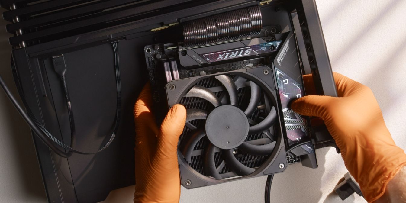
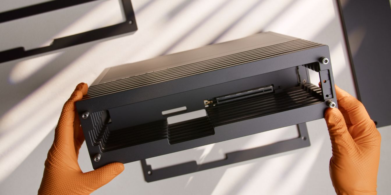
Carefully place the GPU in position, then slowly lower it down.
Check correct alignment by looking through the side of the case, then firmly press the GPU down into the PCIe Gen5 riser slot.
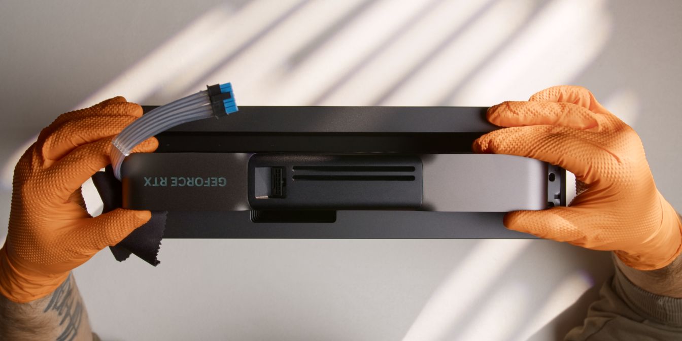
Connect the 12V-2x6 GPU power cable, listening for the audible “click” of the retention latch. Make sure this cable is perfectly seated with no visible gaps.
Add back the plates removed in the previous steps.
The top plate has a machined recess that allows plenty of room for the GPU cable to bend away neatly.
The top panel lightly touching the cable is fine, but if you feel excessive resistance, go back to the PSU cables installation step and pull the GPU cable towards the lower compartment.
And with that, we’re done with assembly 🎉
If you’ve found any mistakes, inaccuracies or missing information, please contact me.