Prep
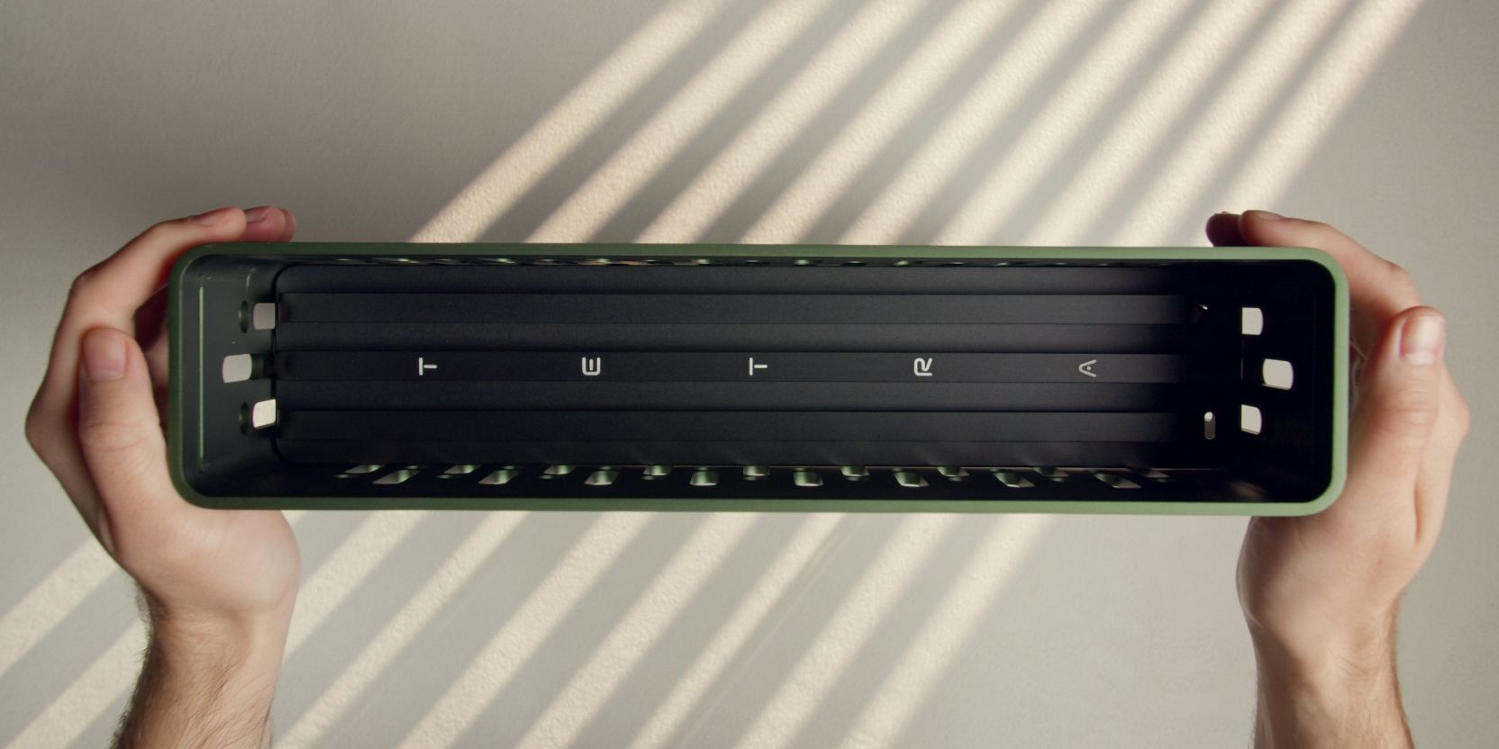
Front Columns
Let’s start with installing the optional walnut front columns.
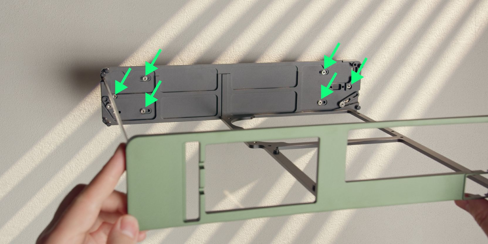
Remove a total of six screws holding the columns attached to the front panel.
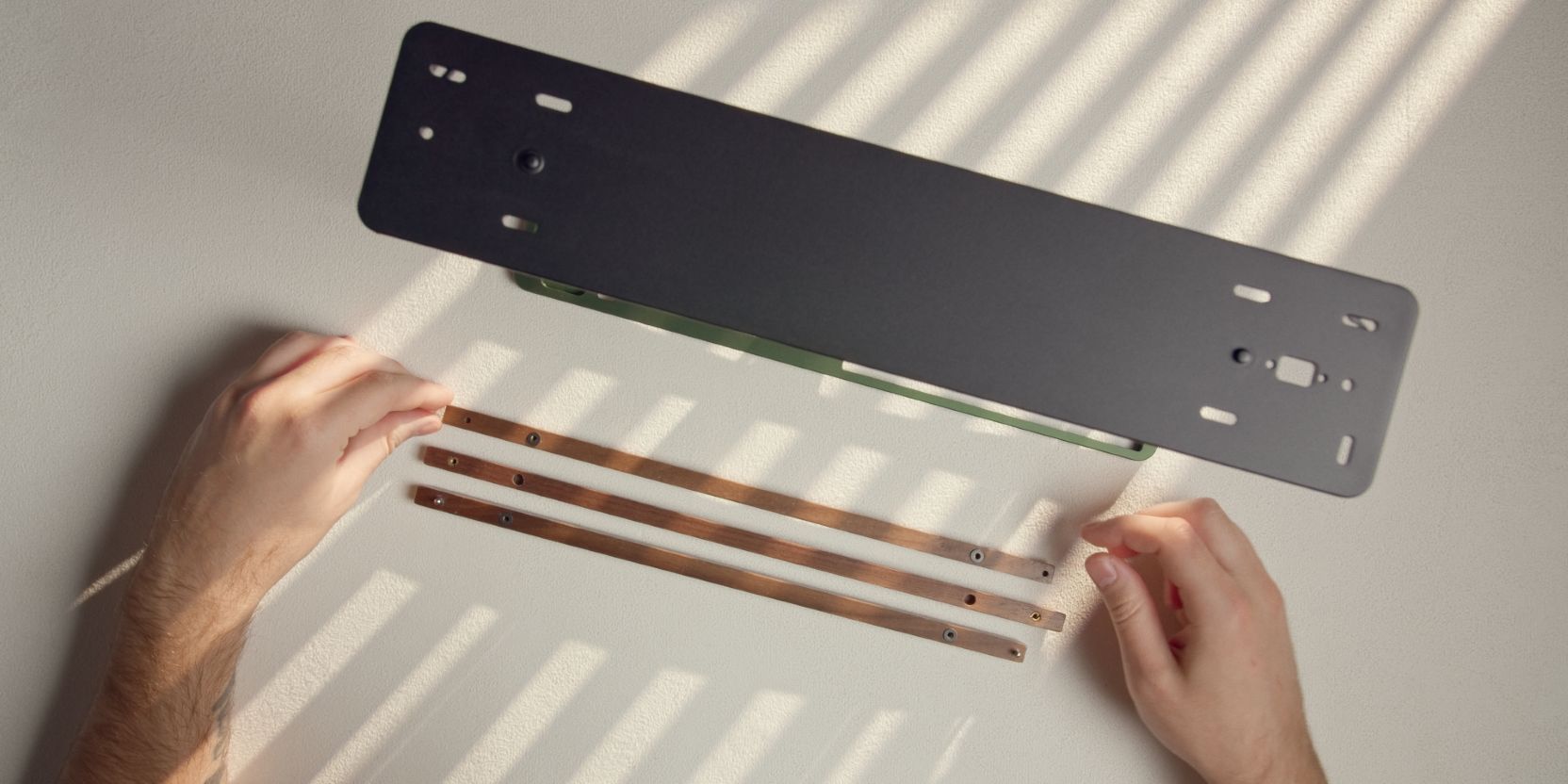
Align the walnut front columns as shown.
Place two washers over the threaded inserts of each of the two outermost columns.
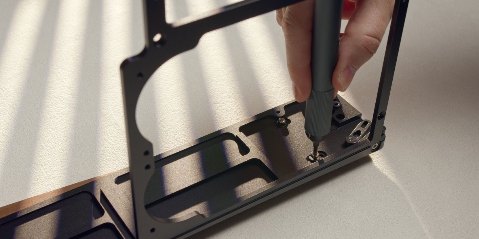
Place the TETRA S core over the front columns, aligning the holes.
Secure the outer columns with two of the socked head screws + washers removed earlier.
Tighten until you feel resistance, then back off slightly. Check if the columns slide freely, adjust the resistance to preference by tightening or loosening both screws.
Secure the center column with two of the countersunk head screws.
Tighten until you feel resistance, then back off slightly.
Power Button
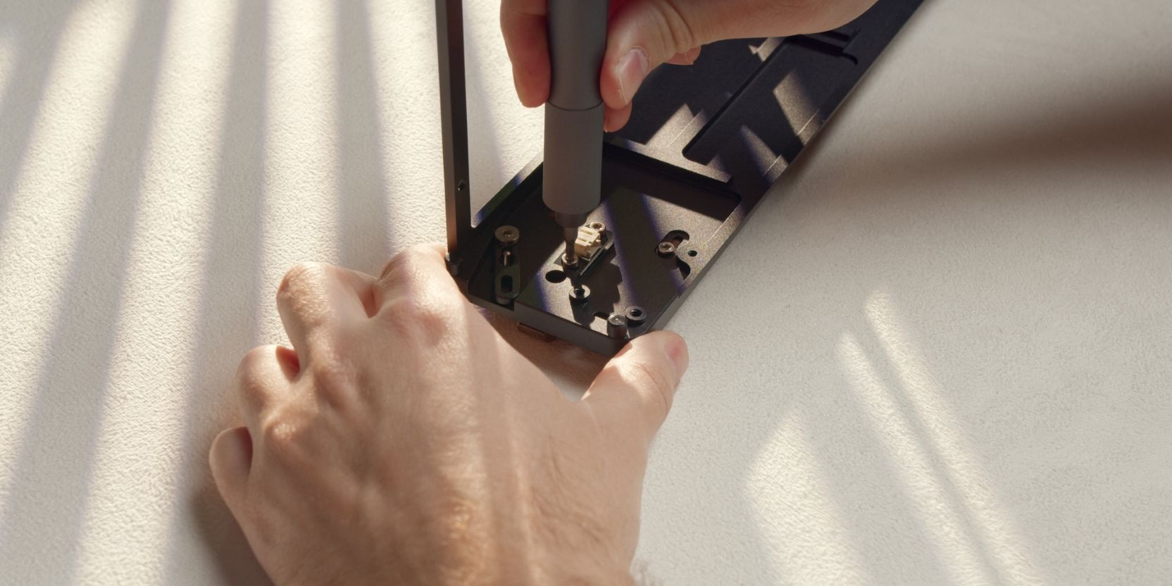
Secure the power button PCB with two M3x5 screws.
Adjust the tightness of the two countersunk head screws holding the center column.
Leave the screw directly next to the power button PCB slightly loose so that the center column can pivot freely. Adjust screw tightness until the power button switch is easily actuated by the front column.
If something feels off, loosen the opposite end screw slightly and re-check.
You want an essentially zero-gap between the front column and the (de-pressed) power button switch.
Type C Cable
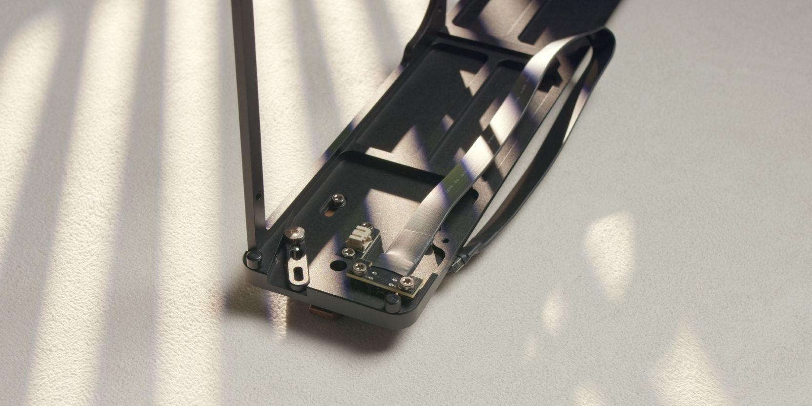
Secure the internal Type C to Type E cable with two M3x5 screws.
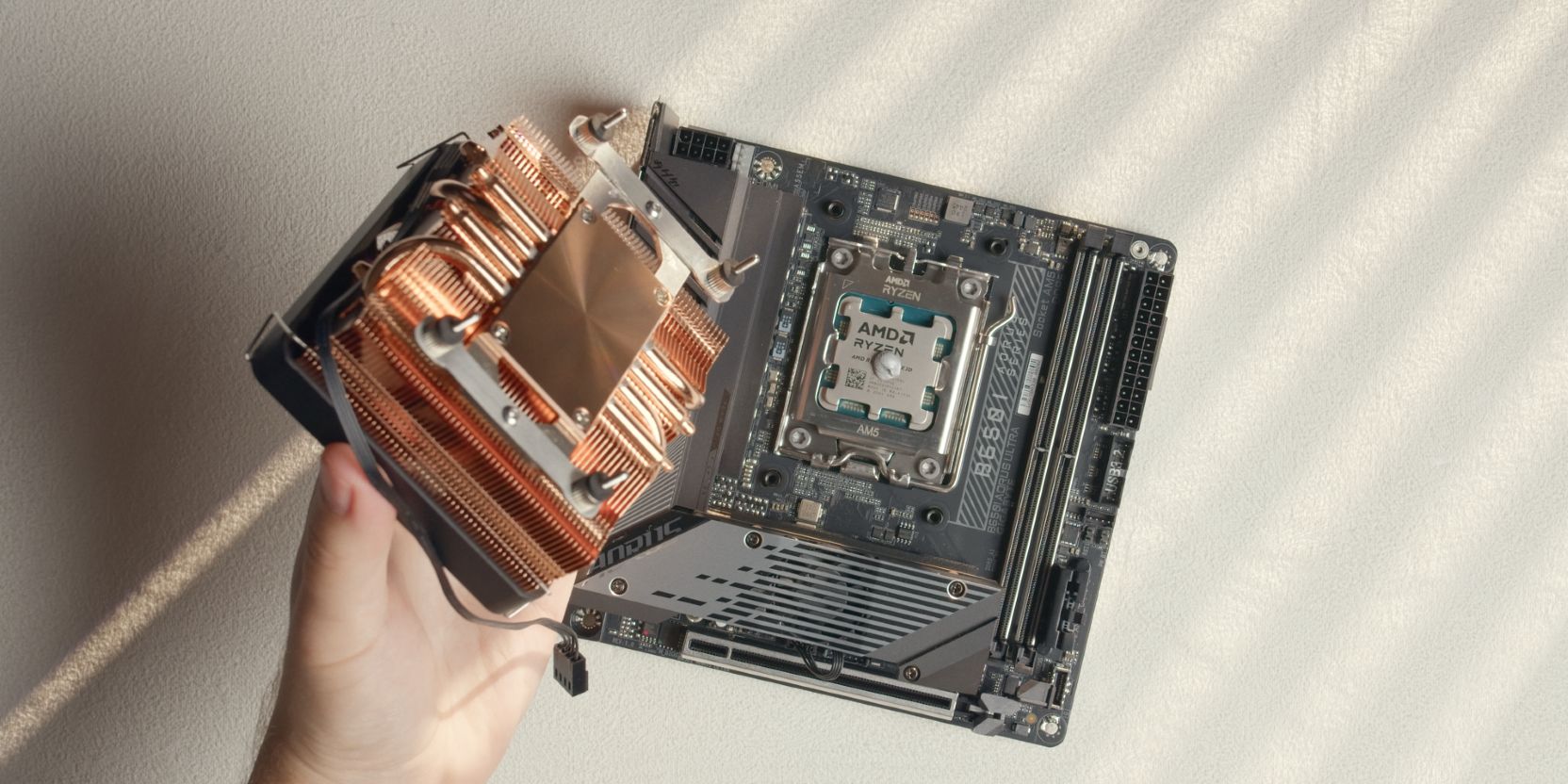
Motherboard
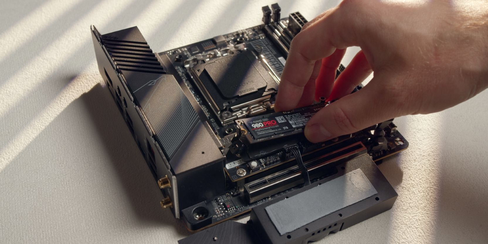
Insert your NVME M.2 drive into the front side M.2 slot of the motherboard.
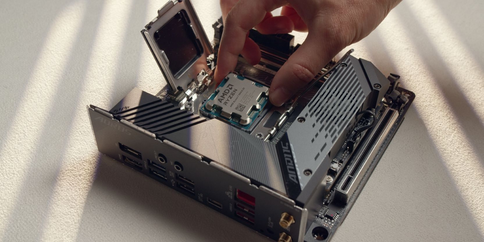
Slot in the AMD Ryzen 7 9800X3D into the AM5 CPU socket.
CPU Cooler
Let’s prepare the AXP90 Full Copper cooler for installation by removing the stock Intel brackets.
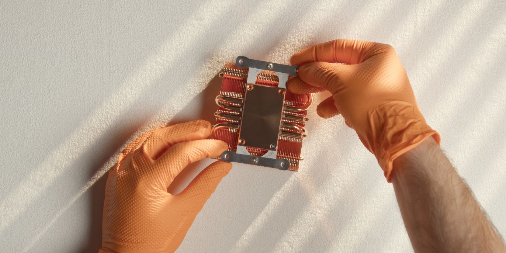
Secure the DingKey offset brackets using the same Philips head screws removed during the previous step.
If you skipped the offset brackets, secure the supplied AMD brackets instead.
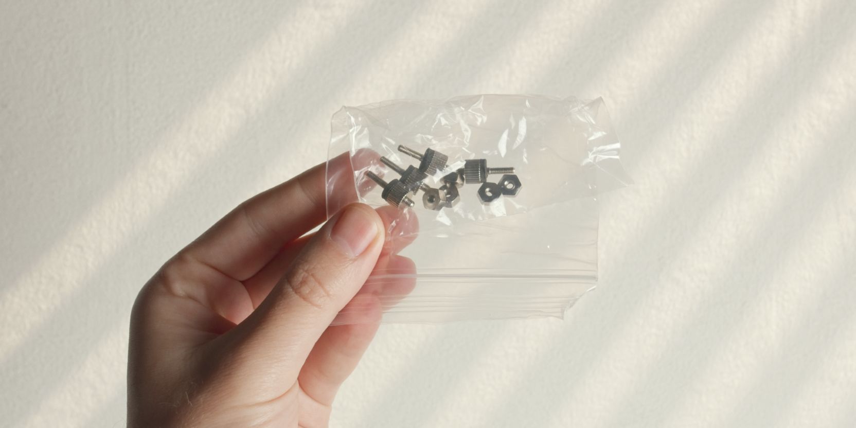
The AXP90 comes with two sets of thumb screws. We need the shorter set of screws, which should come packed together with the nuts in an individual bag.
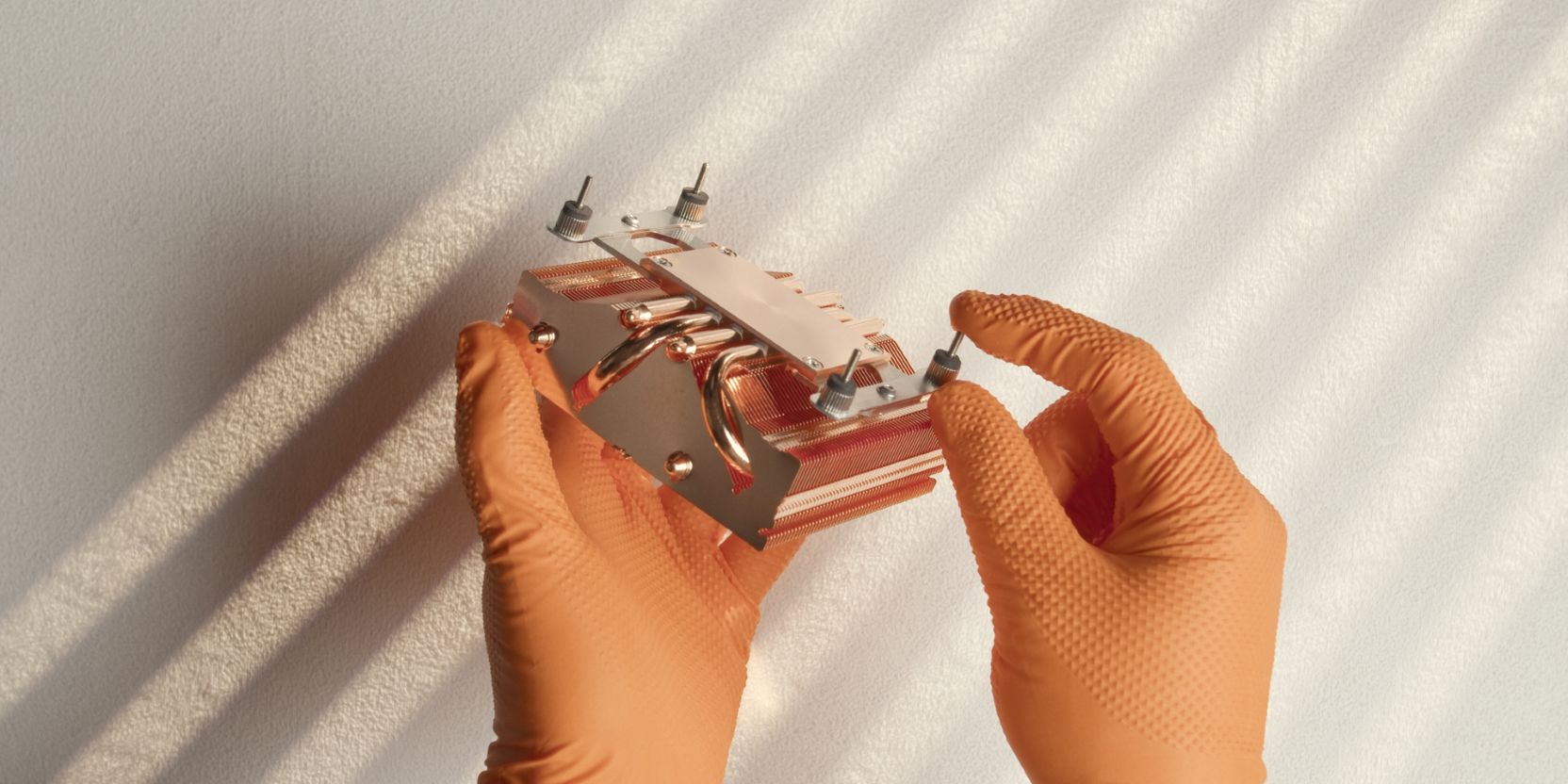
Secure the short thumb screws to the brackets as shown. Finger tight is fine.
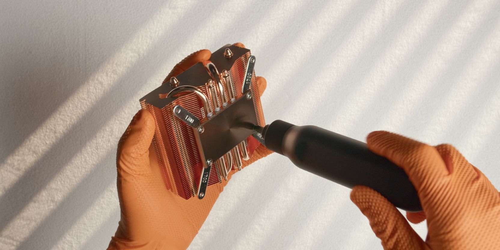
Place a pea-sized drop of thermal paste onto the center of the CPU heat spreader. A more uniform method would be to use a cross pattern but I find I’m less consistent with that method between applications.
Place the heatsink onto the CPU with the longer offset bracket towards the north (up) part of the motherboard.
Make sure that the screws are aligned with the AM5 backplate threaded posts and feed them through simultaneously, keeping the heatsink as level as possible.
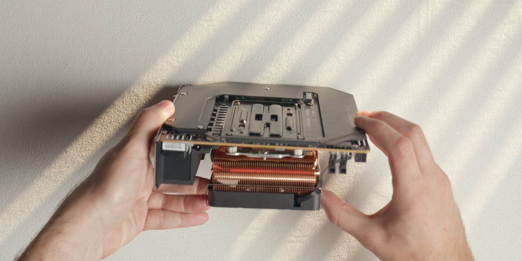
Flip over the assembly, making sure to hold the cooler in position and maintain pressure so that it doesn’t back out of the AM5 mounting posts.
Hand tighten the included nuts onto the screws just enough so that the cooler won’t come off.
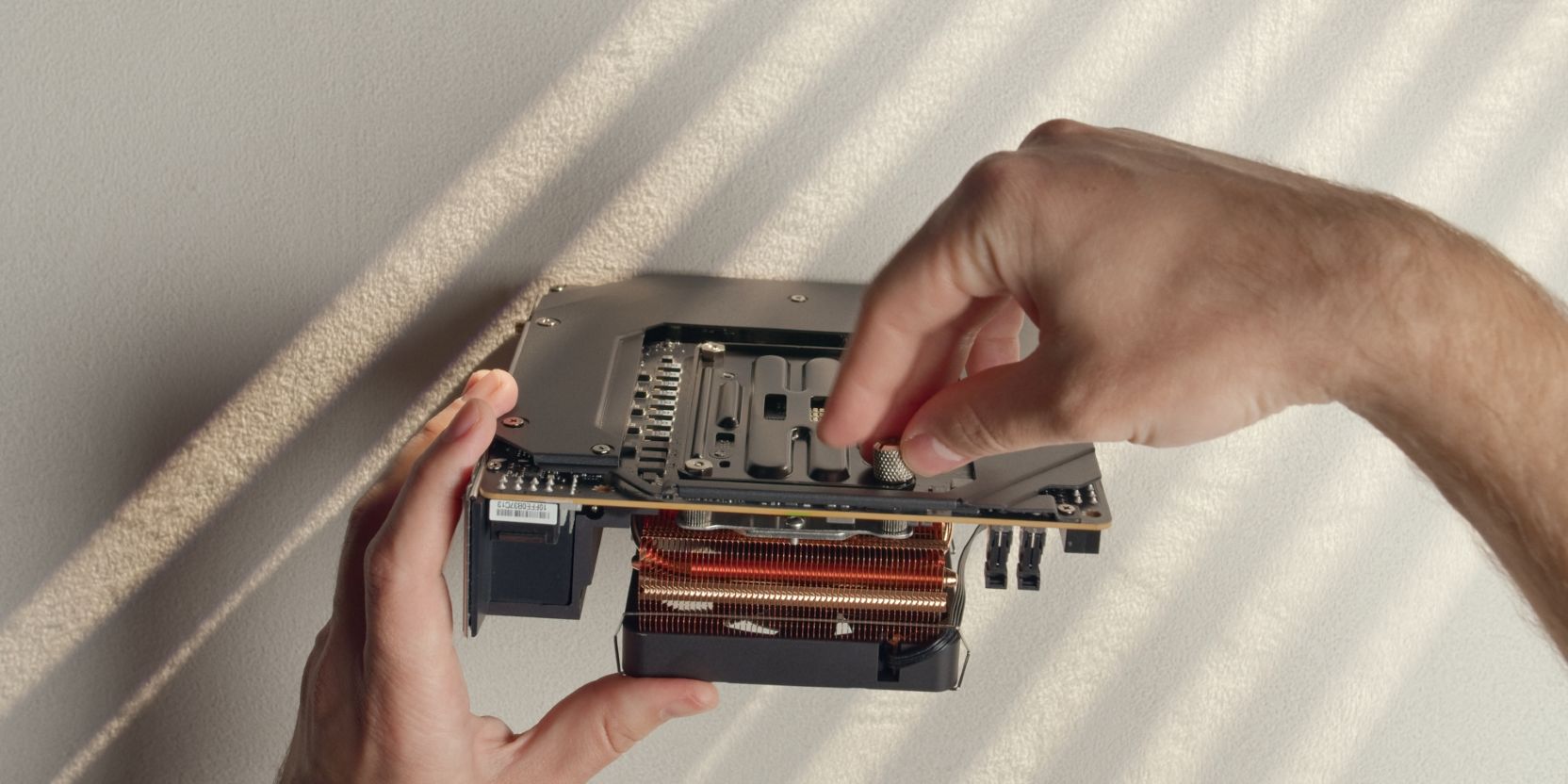
Continue tightening the nuts using the included thumb screw tool.
This will be easy to see on the motherboard’s north side, but very difficult on the opposite side as the leaf spring will be obstructed by the NVME heatsink.
I tend to go by feel here, going for an even tightness across all four nuts.
You can also look at how much each screw is protruding inside the nuts and have them all sit at about the same depth, although keep in mind that screw length may vary.
CPU Fan
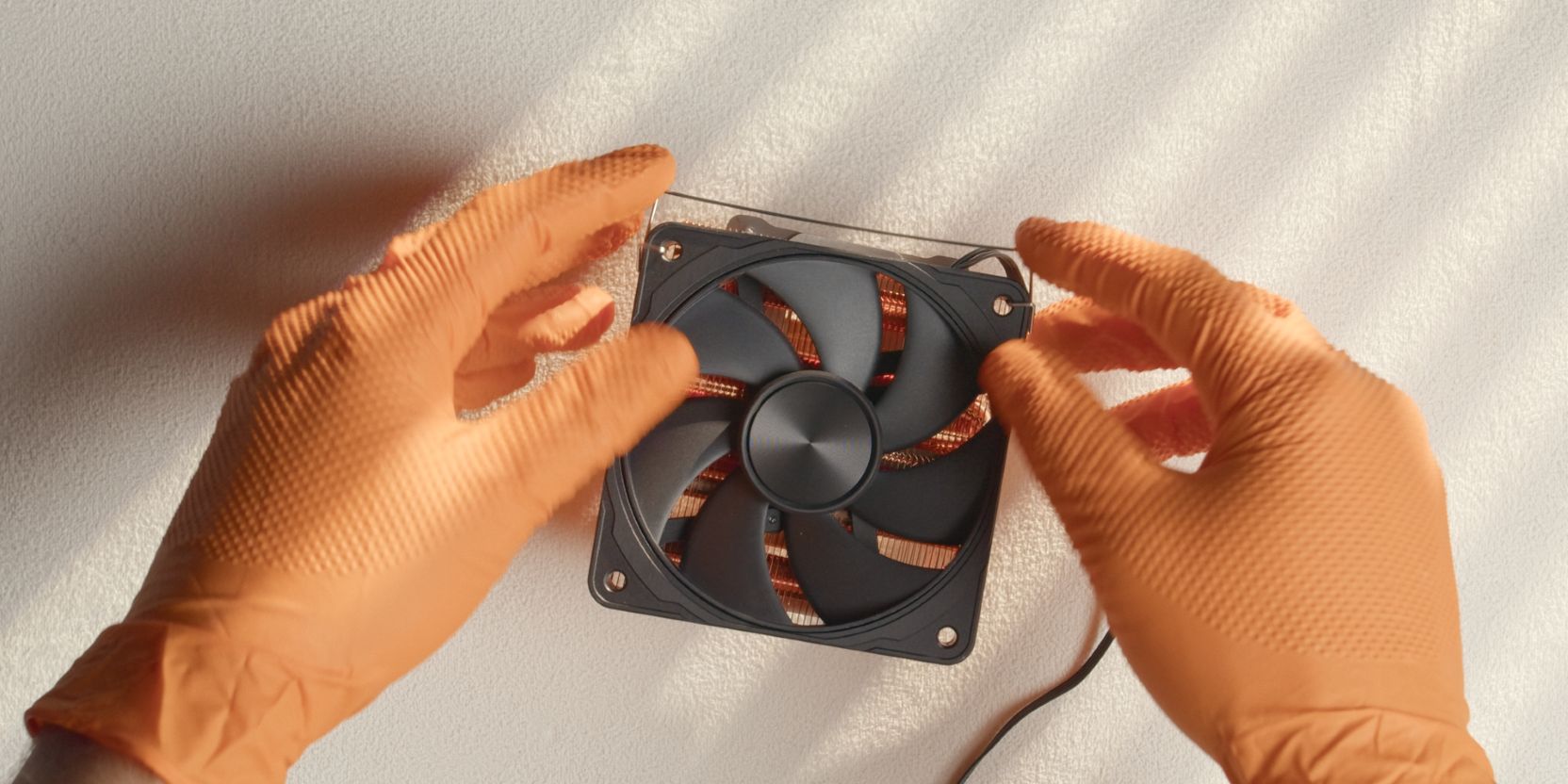
Install the 4070 CNC fan on top of the heatsink using the stock fan clips. The 4070 CNC frame fan is larger, but the clips should still work fine with a bit of elbow grease 🙃.
You can also stick with the included fan if you don’t mind the orange color scheme (I mind).
RAM
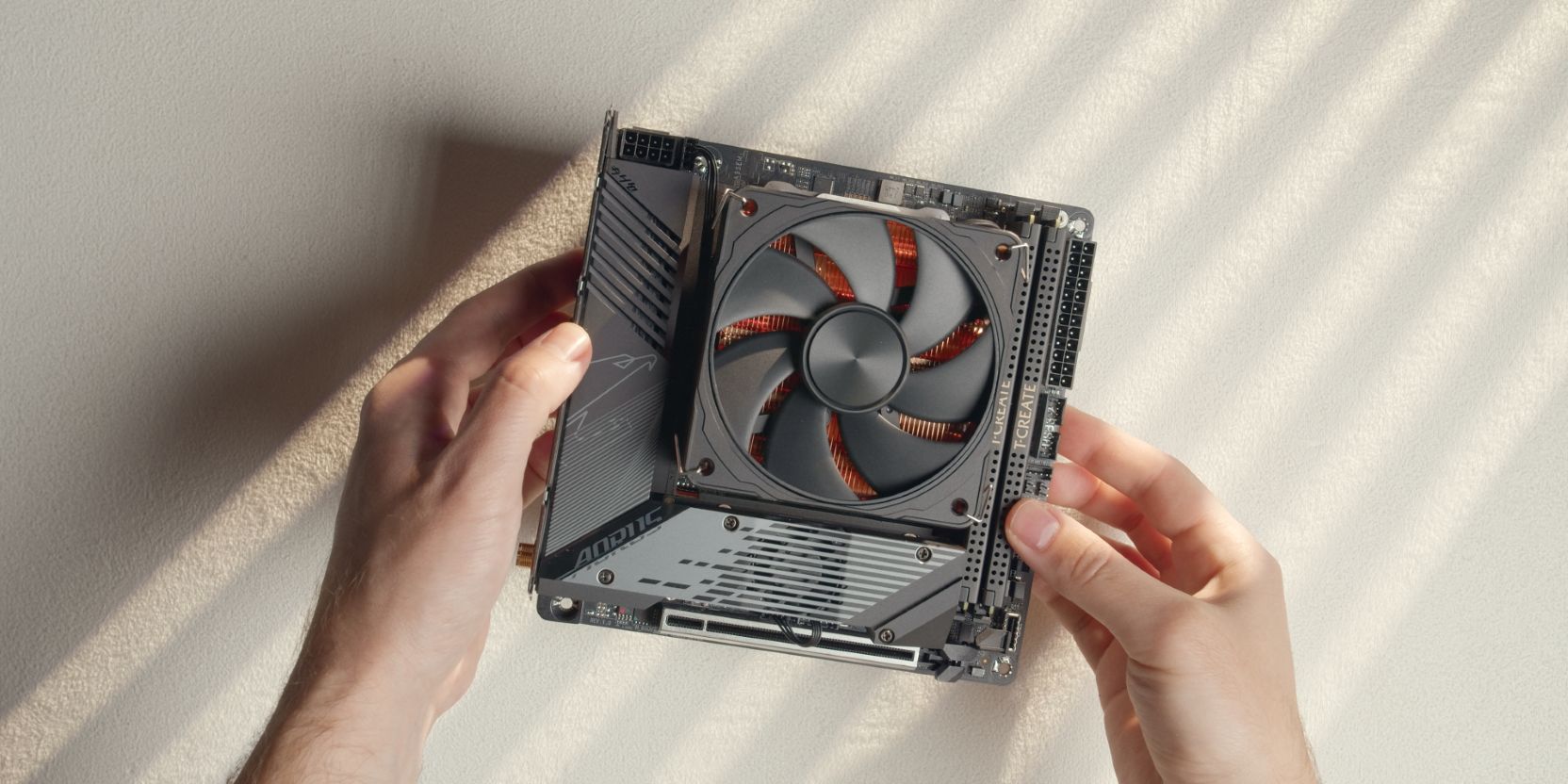
Slot in the RAM modules into the motherboard DIMM slots.
Your end result should look similar to the reference image above. Double check that you’ve installed the cooler with the longer brackets towards the top (north) of the motherboard.
GPU Riser
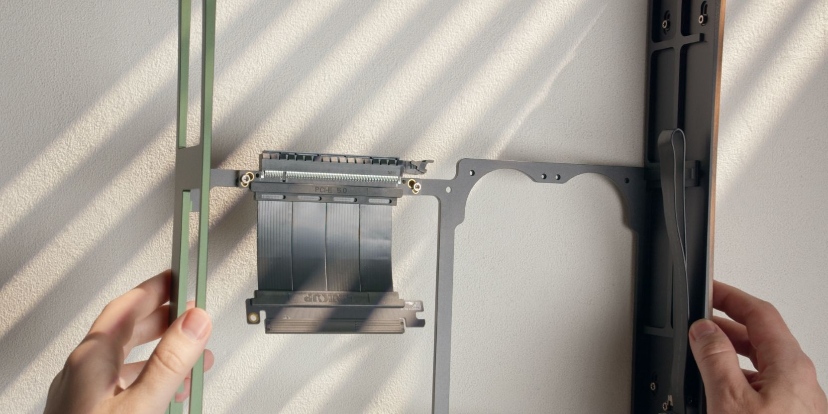
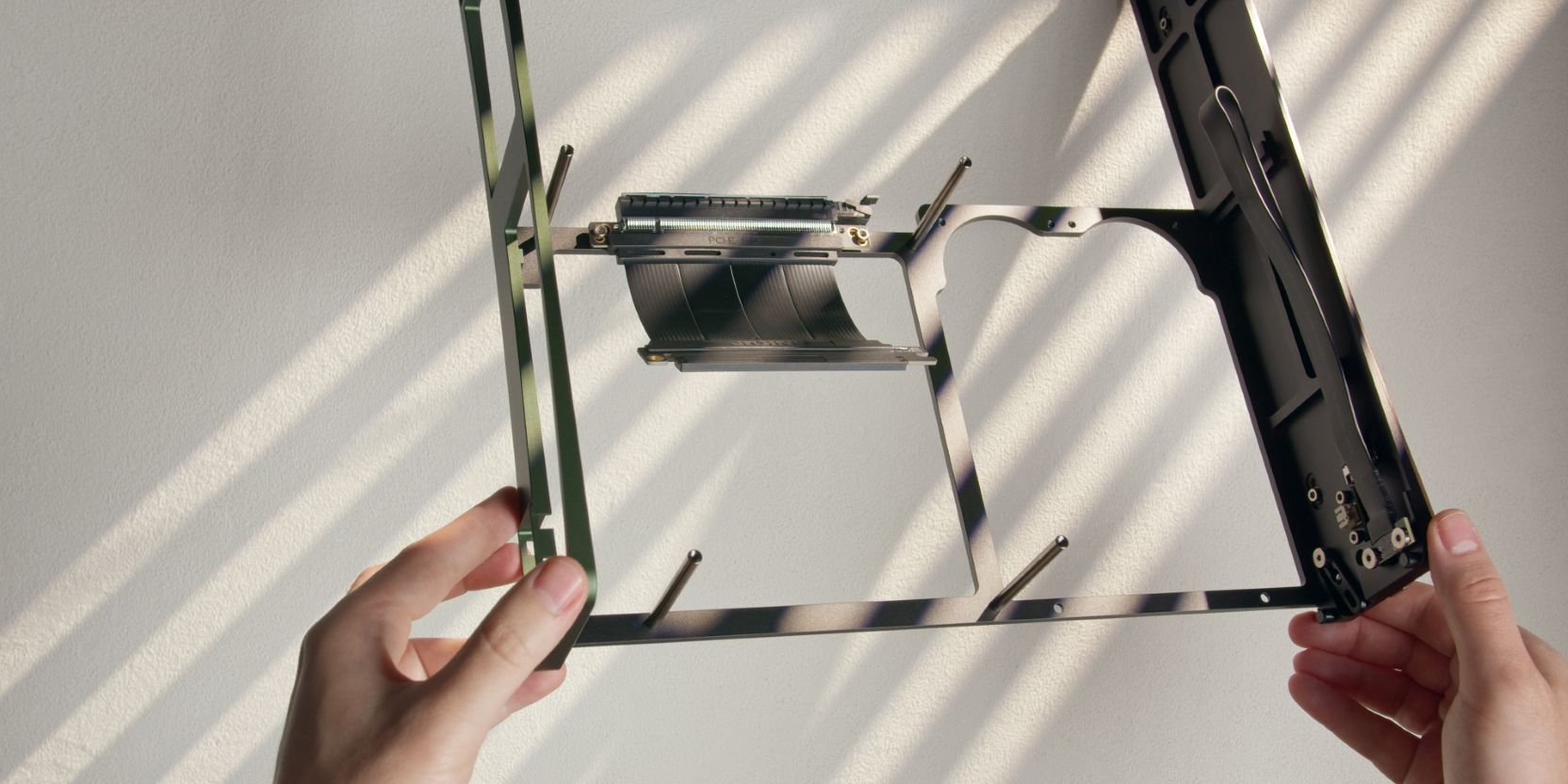
Position the included PCIe Gen5 riser as shown and secure it with two M3x5 screws.
Remove the plastic protective insert from the GPU end of the riser.
MB Standoffs
Install the four motherboard standoffs and secure them with four #6-32x0.3125 countersunk head screws.
Power cord
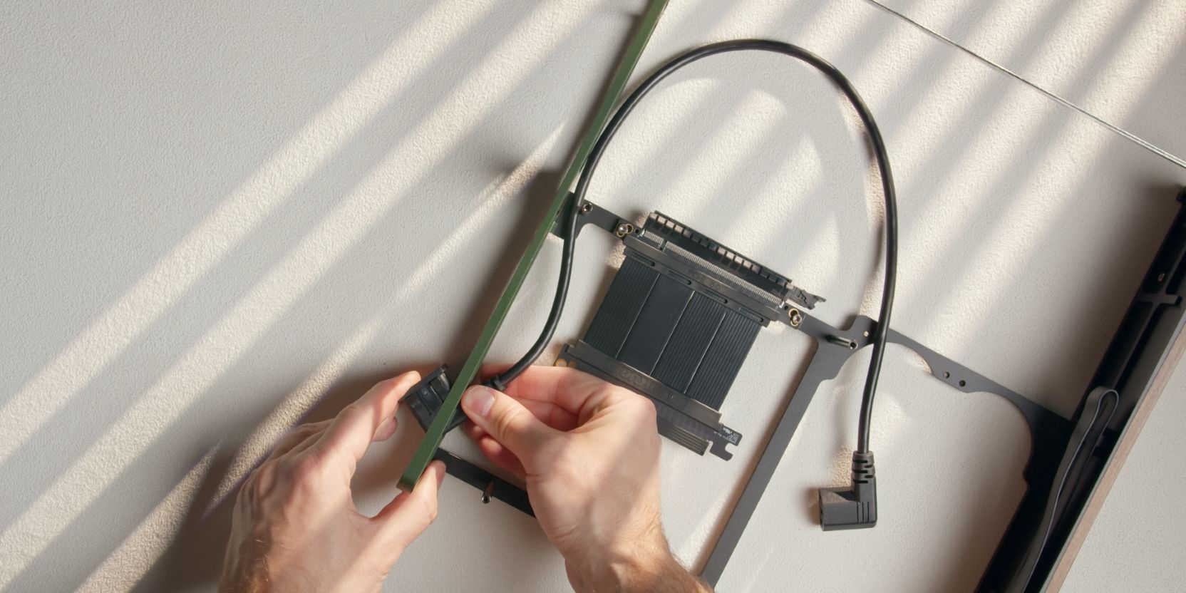
Insert the internal PSU power cable through the cutout in the rear panel.
Orient the inlet plug as shown, with the 90 degree elbow facing up (relative to the case).
The plug will click in place when it is fully inserted.
You are now ready for the Assembly part of the guide.