Assembly
The steps below assume you’ve already prepped everything for installation.
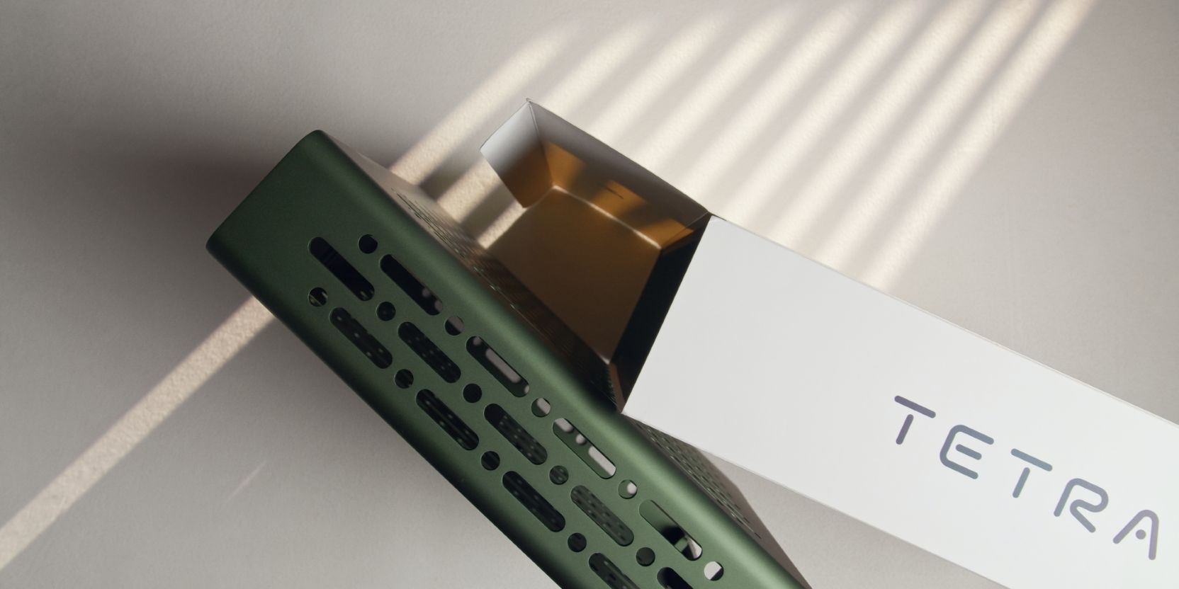
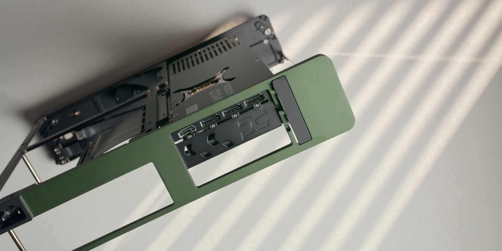
GPU
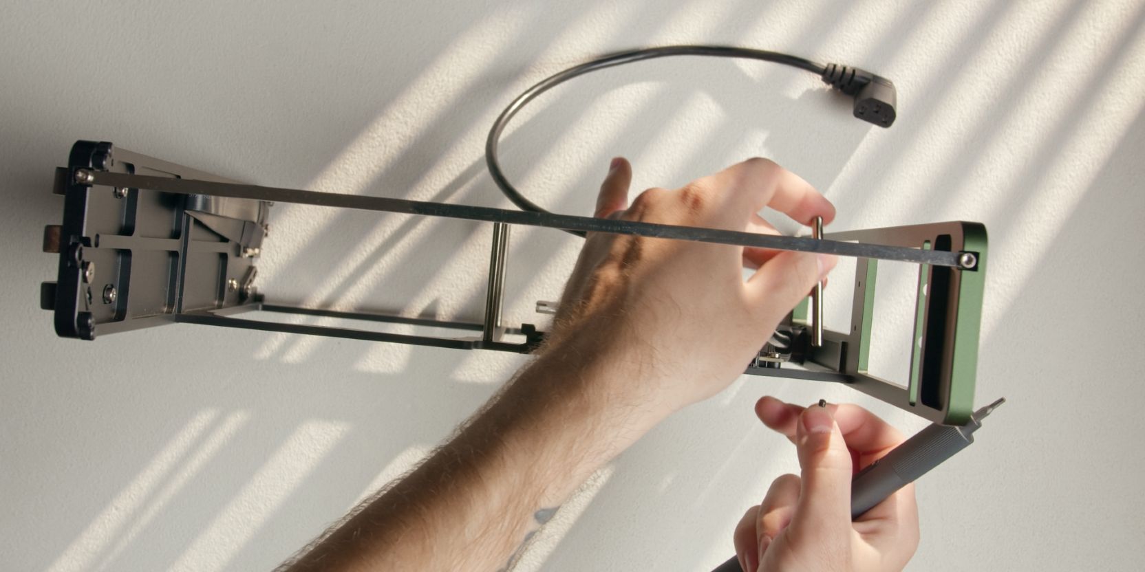
I know you just secured this standoff during a previous step, but let’s remove it in order to make our lives easier when securing the GPU.
At least now you know where it goes 😊.
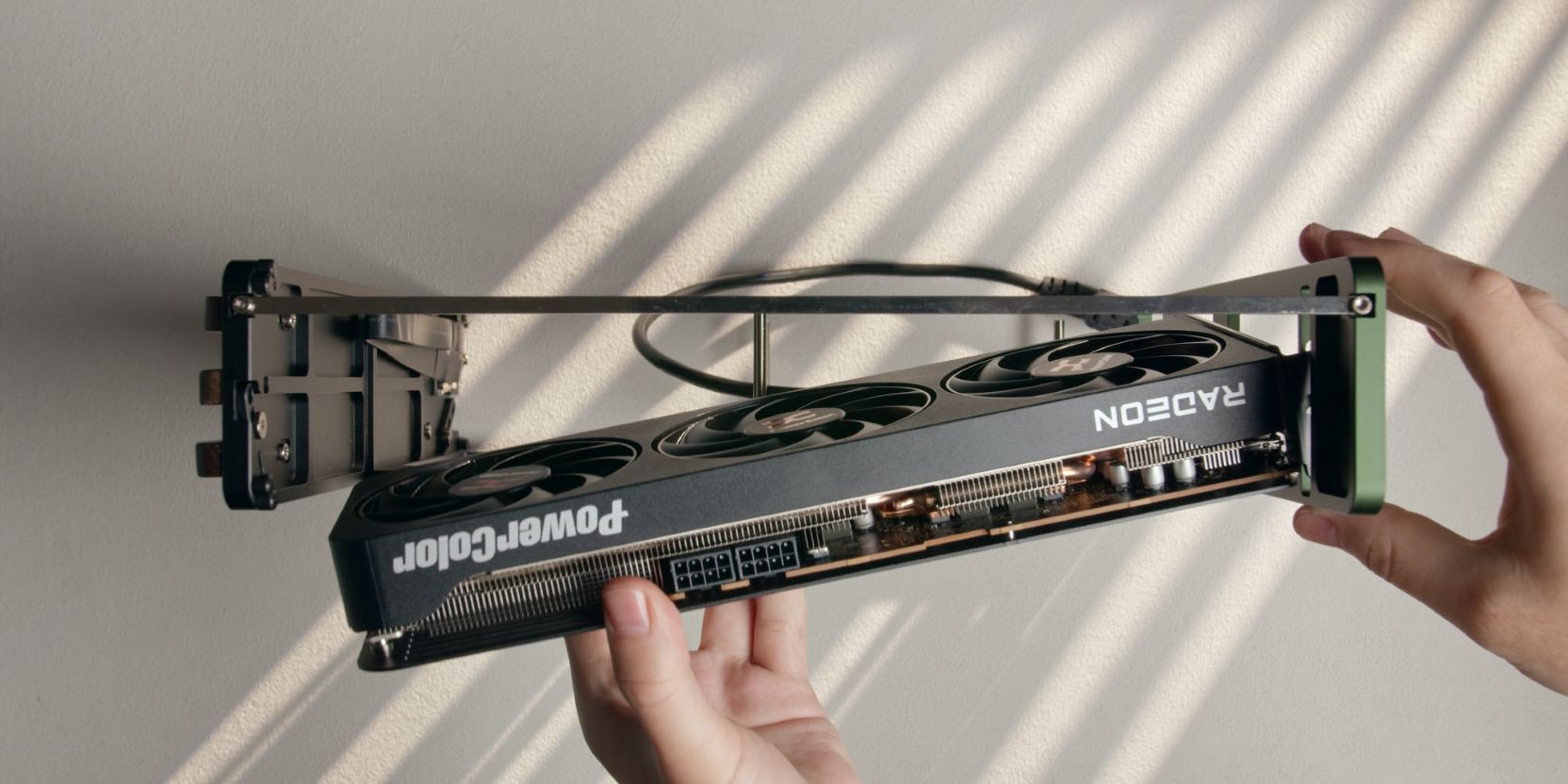
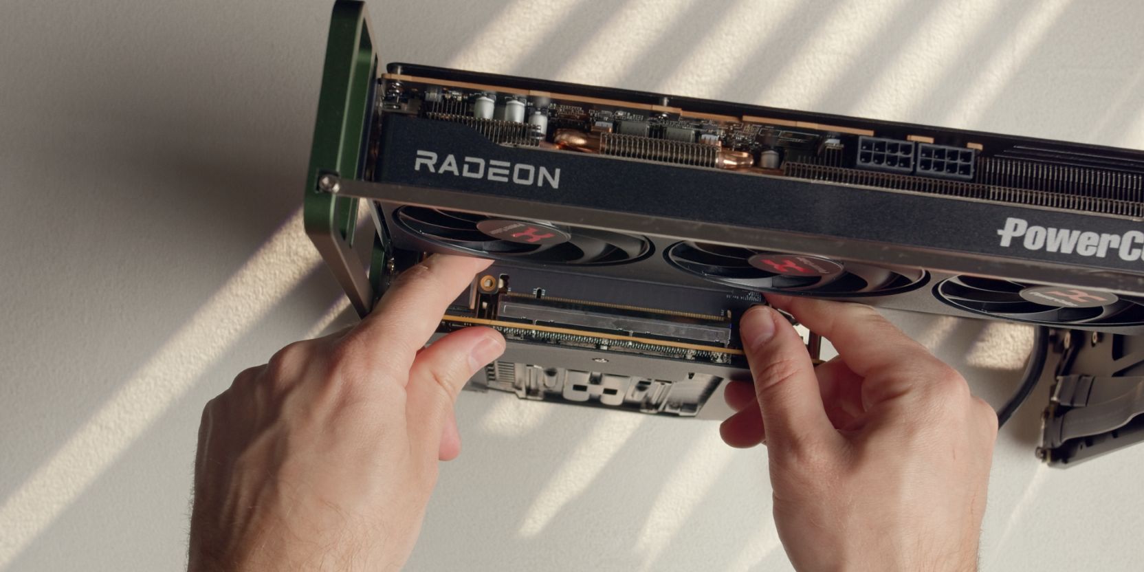
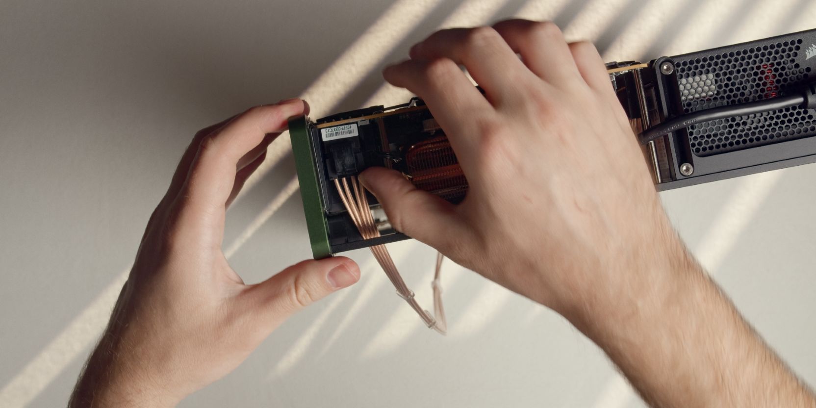
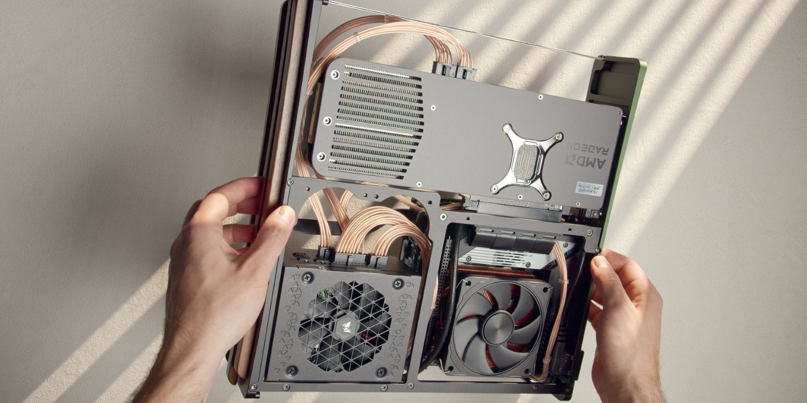
Insert the GPU at an angle in order to clear the front panel, then align the PCIe connector with the riser below and slot it in until the retention latch engages with an audible click.
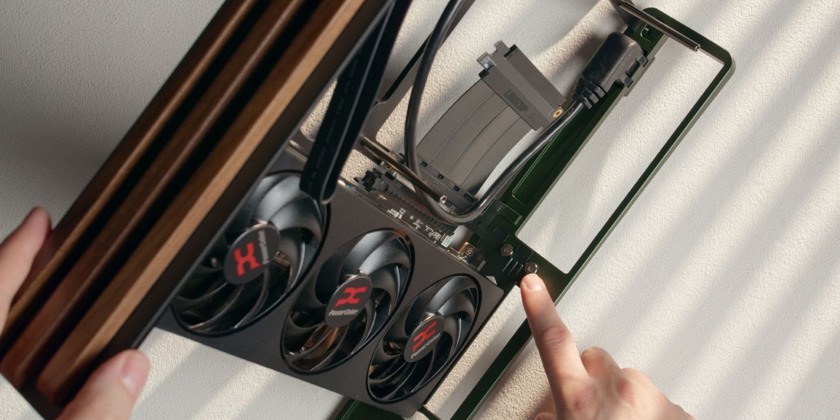
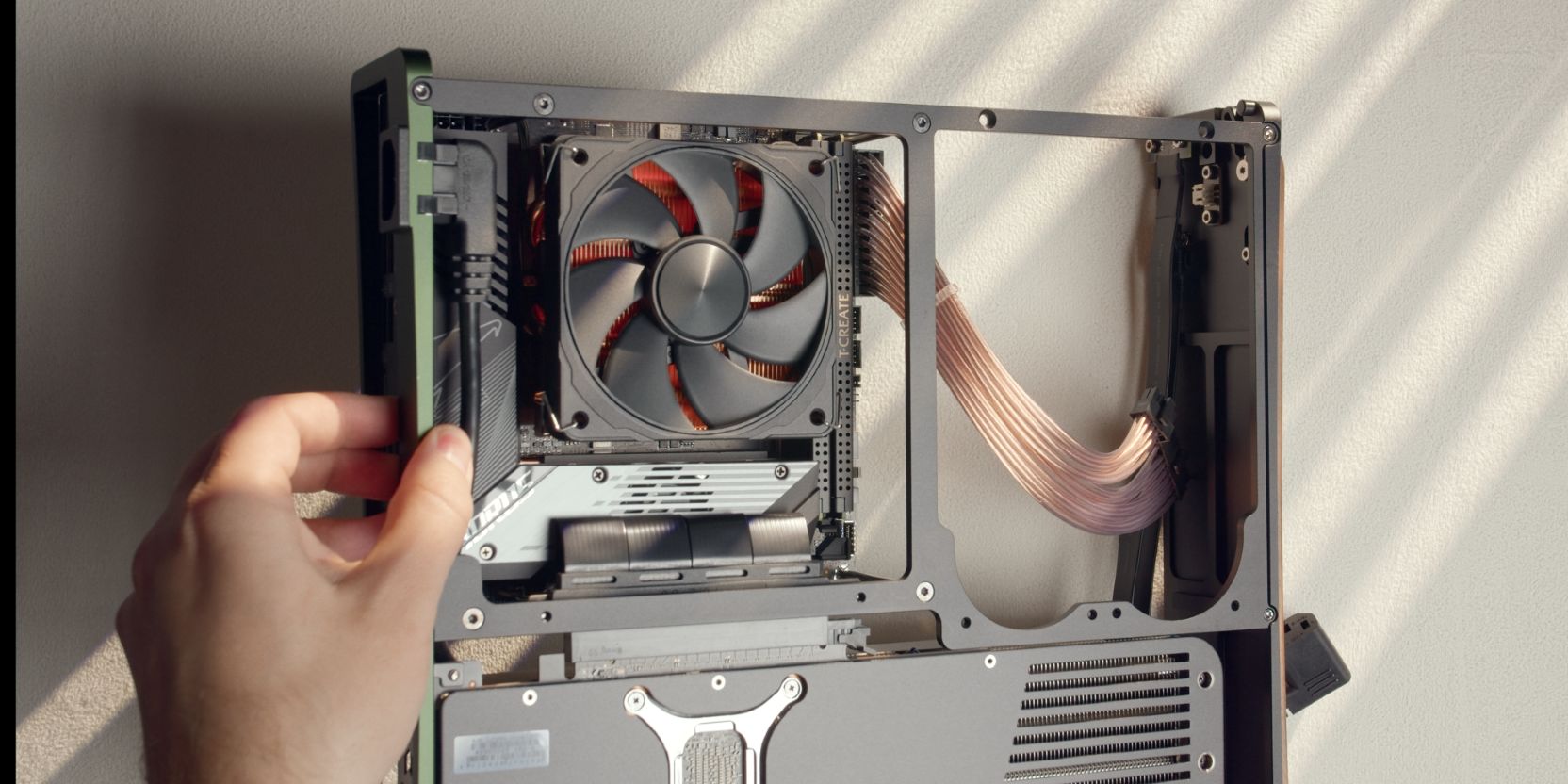
Secure the two slot GPU I/O bracket to the case using two of the included M3x4 “large head"screws.
Insert the GPU lock bar piece in the empty space above the GPU I/O bracket.
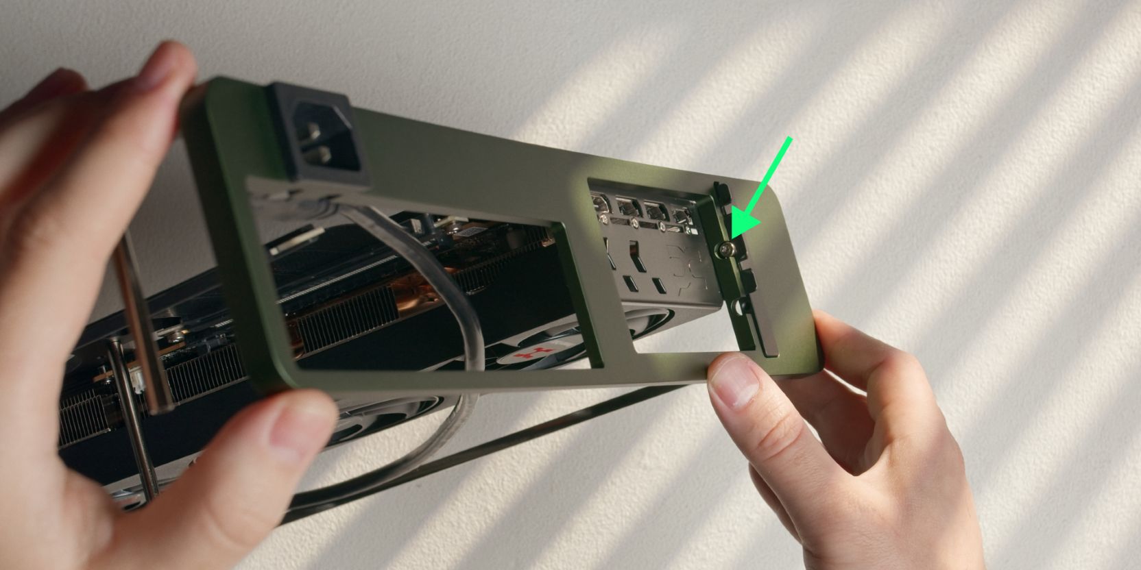
Secure the lock bar with a single M3x5 socket head screw.
You can add the other screw as well but I did not find it necessary.
Motherboard
In order to make our lives easier when adding the motherboard onto the standoffs, let’s pre-bend the riser.
Try to give it a U shaped bend with the PCIe connector facing “upwards” at a near 90 degree angle.
The TETRA cases feature an unusual “upside-down” motherboard mounting system.
Pay attention to the long standoffs installed during the prep step.
Place the motherboard facing downwards, onto the standoffs.
Make sure the I/O shield of the motherboard is sitting snugly into the rear motherboard cutout and verify that the standoffs are aligned with the mounting holes.
Secure the motherboard with four of the short #6-32x0.25in button head screws.
I recommend loosening and re-tightening the standoff screws after securing the motherboard, then doing the same on the motherboard back side, just to get everything properly settled.
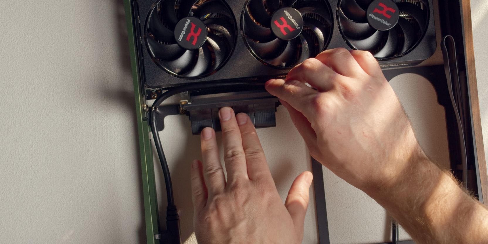
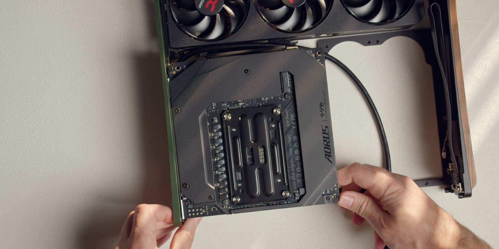
Finally let’s connect the riser cable to the motherboard.
If you pre-bent the riser cable correctly, it should line up relatively nicely with the motherboard’s PCIe slot.
Get your index fingers in there and pull the riser connector towards the slot and insert it until the retention latch makes an audible click.
Connect the 24 pin PSU cable to the motherboard. It’s easier to do this now, prior to adding in the PSU.
Do the same for the internal Type C to Type E cable and the power button cable.
Route both cables as shown.
Type E internal cables (or the Devil’s spawn) are keyed so that they only go in one way, or so they say.
When connecting, don’t force them in, they should connect fairly easily with a distinct click sound.
PSU
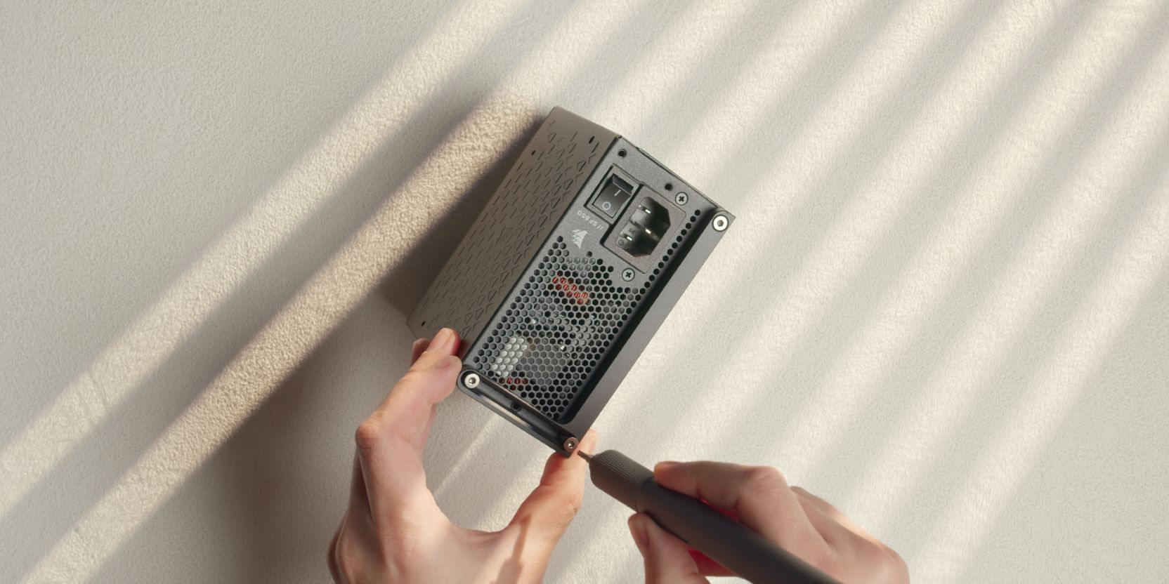
Secure the PSU bracket onto the power supply with three #6-32x0.4375in countersunk head screws included in the TETRA accessory box.
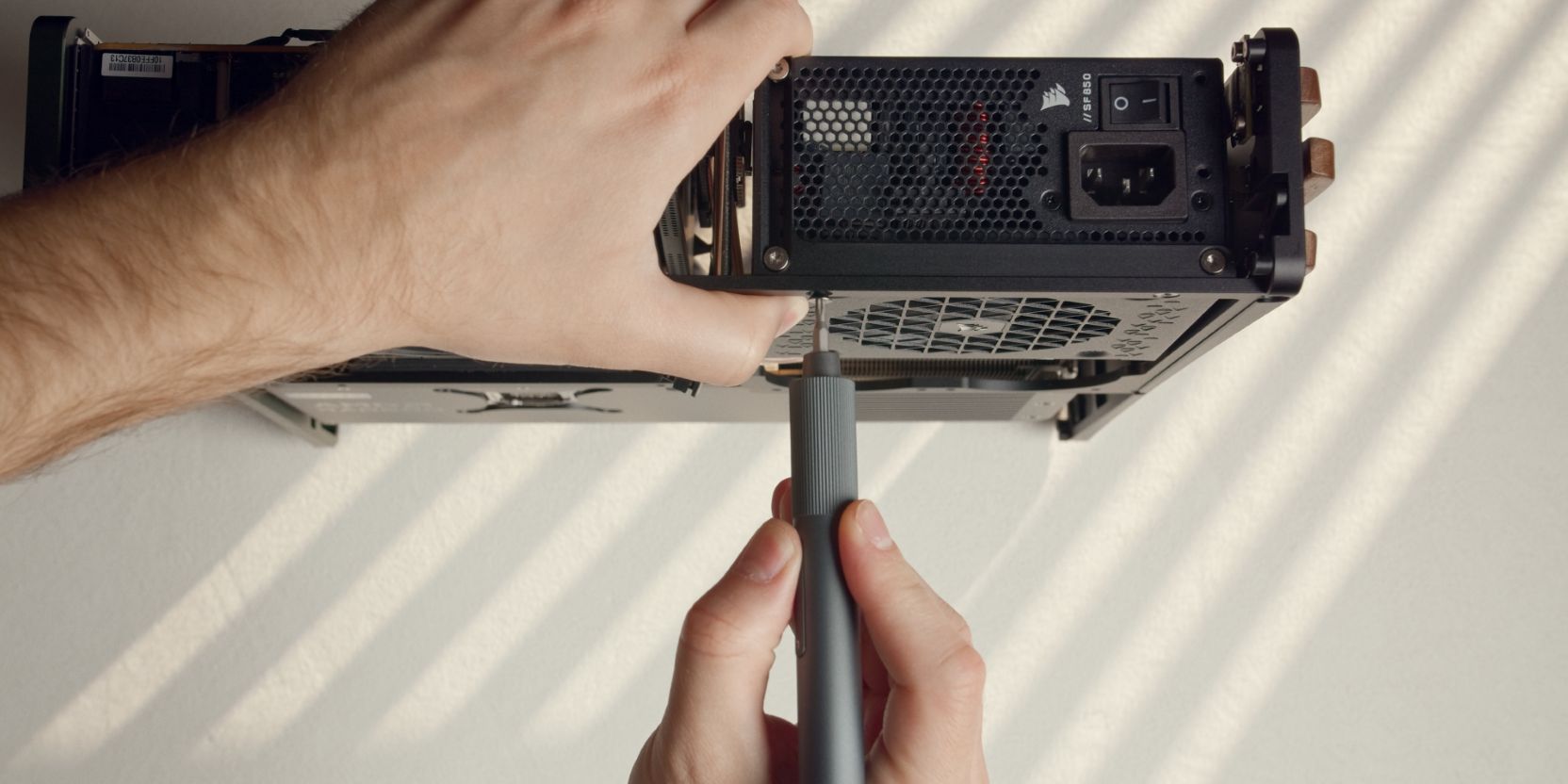
Secure the assembly onto the TETRA core with two #6-32x0.3125in (shorter ones) countersunk head screws.
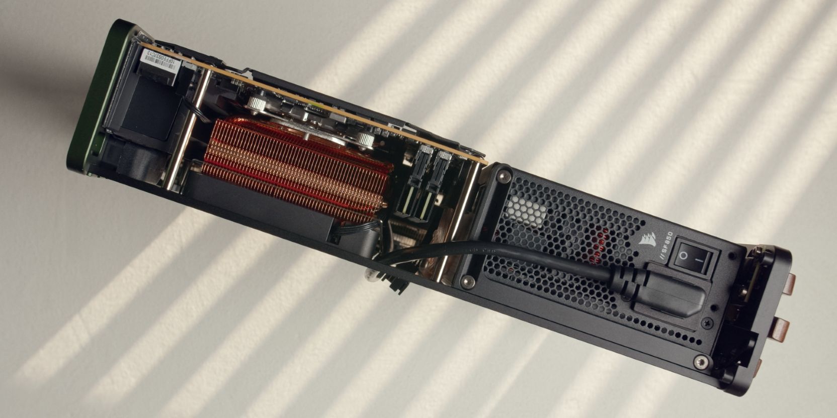
Route the internal power cable as shown, going upwards alongside the RAM modules and over the top right motherboard standoff.
Check how I routed the power cable in the motherboard step. It goes up alongside the VRM heatsink of the motherboard, then up and over in between the motherboard and the GPU.
Plug in the power cable and switch the power supply power button to the “On” position.
PSU Cables
Connect the Type 5 ends of the 24 pin motherboard cable added earlier to the Corsair SF850 power supply.
Connect the 8 pin CPU power cable to the motherboard.
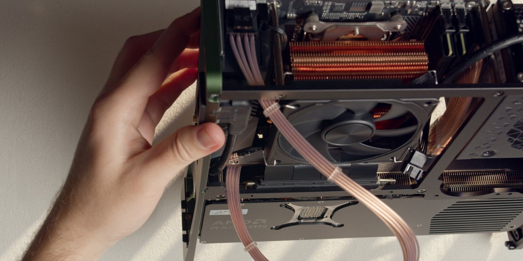
I chose to route the CPU cable alongside the PSU power cable, across the motherboard’s VRM heatsink, then down alongside the edge of the GPU.
Connect the Corsair Type 5 ends of the CPU power cable to the PSU.
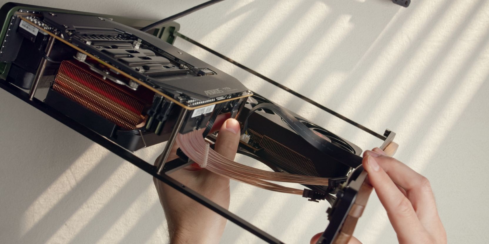
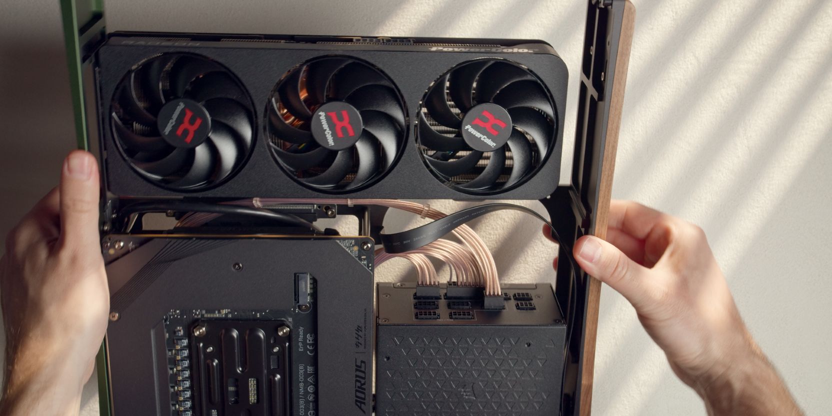
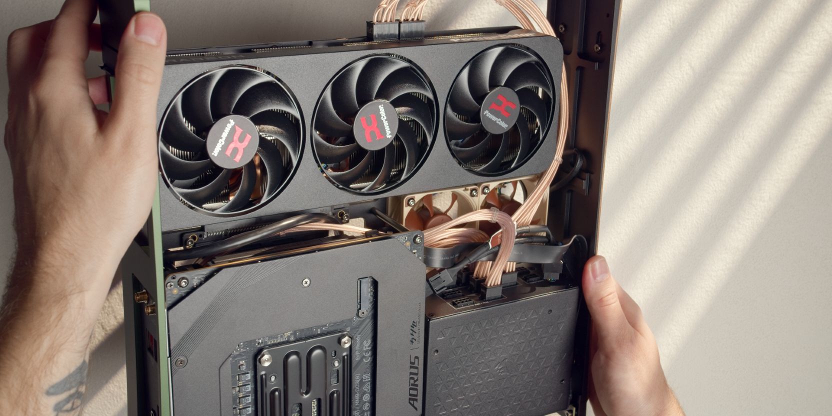
Connect the GPU 8 pin power cables and route them as shown.
For a 9070 XT It’s best to use two individual 8 pin cables instead of a single one that splits into two connectors at the GPU end.
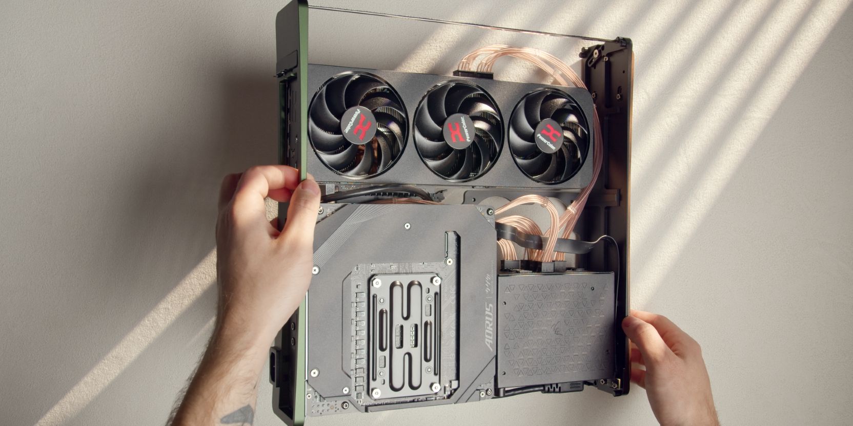
Your cable management should end up looking similar to this.
It’s important to avoid having loose cables that hang off to either side, so keep them as contained as possible. This will avoid any cable snags when sliding the shell back on.
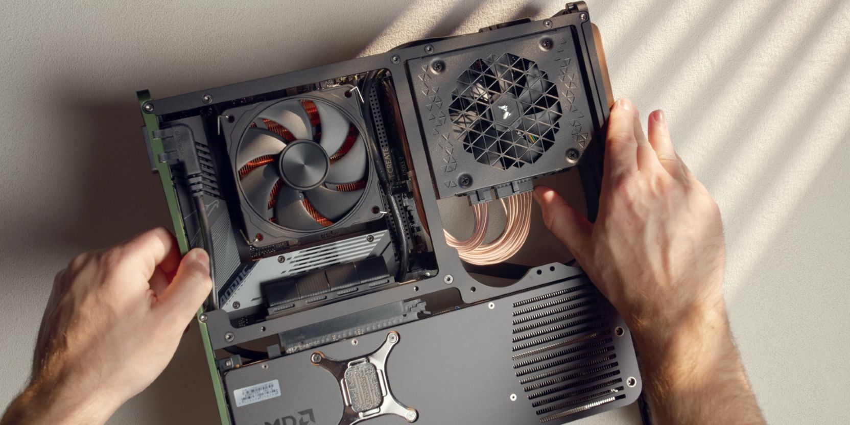
Case Fans
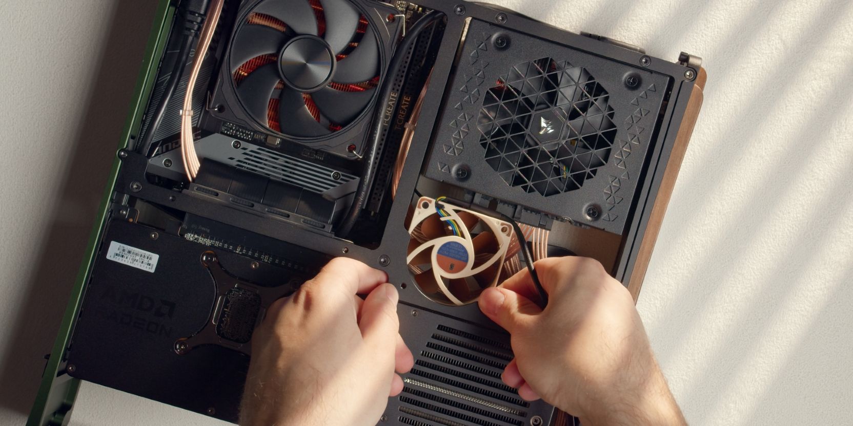
The TETRA S can be fitted with two 60mm case fans that help move air around.
Installation of these can be difficult, as they push slightly against the PSU cables and connectors.
Start with one fan, holding it in position while you secure it with two long #6-32x0.75in button head screws.
Add the other fan.
Use the included Noctua Y-splitter adapter cable (NA-SYC1) to connect both fans together, then connect it to a fan header on the motherboard. Use the included 30cm extension cable if needed.
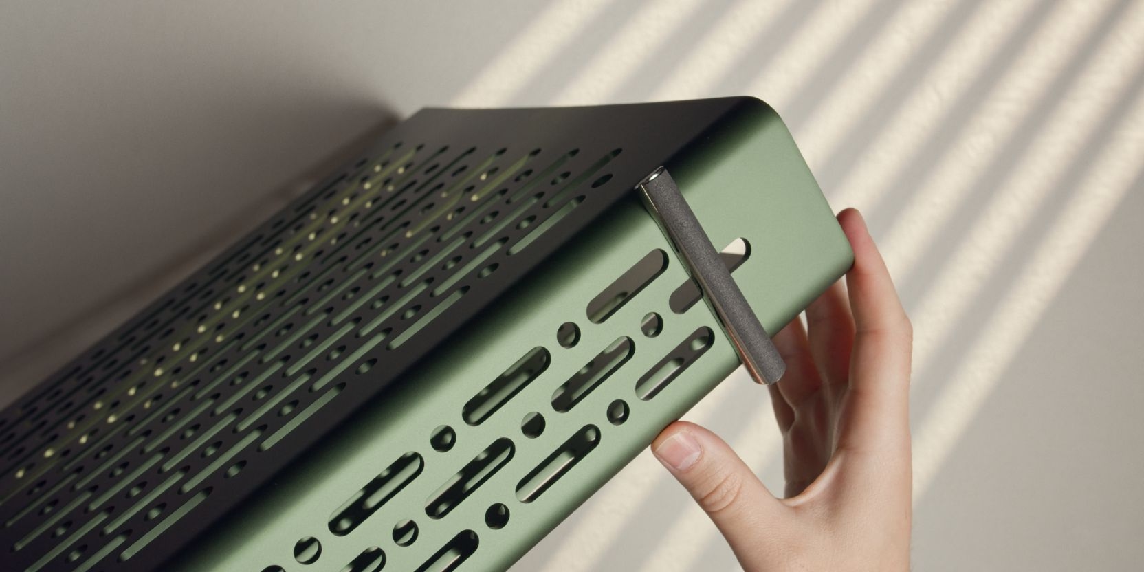
Stands
If you purchased the optional chrome stands, you need to secure them from inside the shell.
Secure them each with two M3x4 “large head” screws and two washers.
If you skipped the chrome stands, you can use four of the included rubber pads as simple feet.
There should also be a small roll of foam tape included in the accessory box of the TETRA.
Cut strips matching the length of the chrome bars and stick them on as shown.
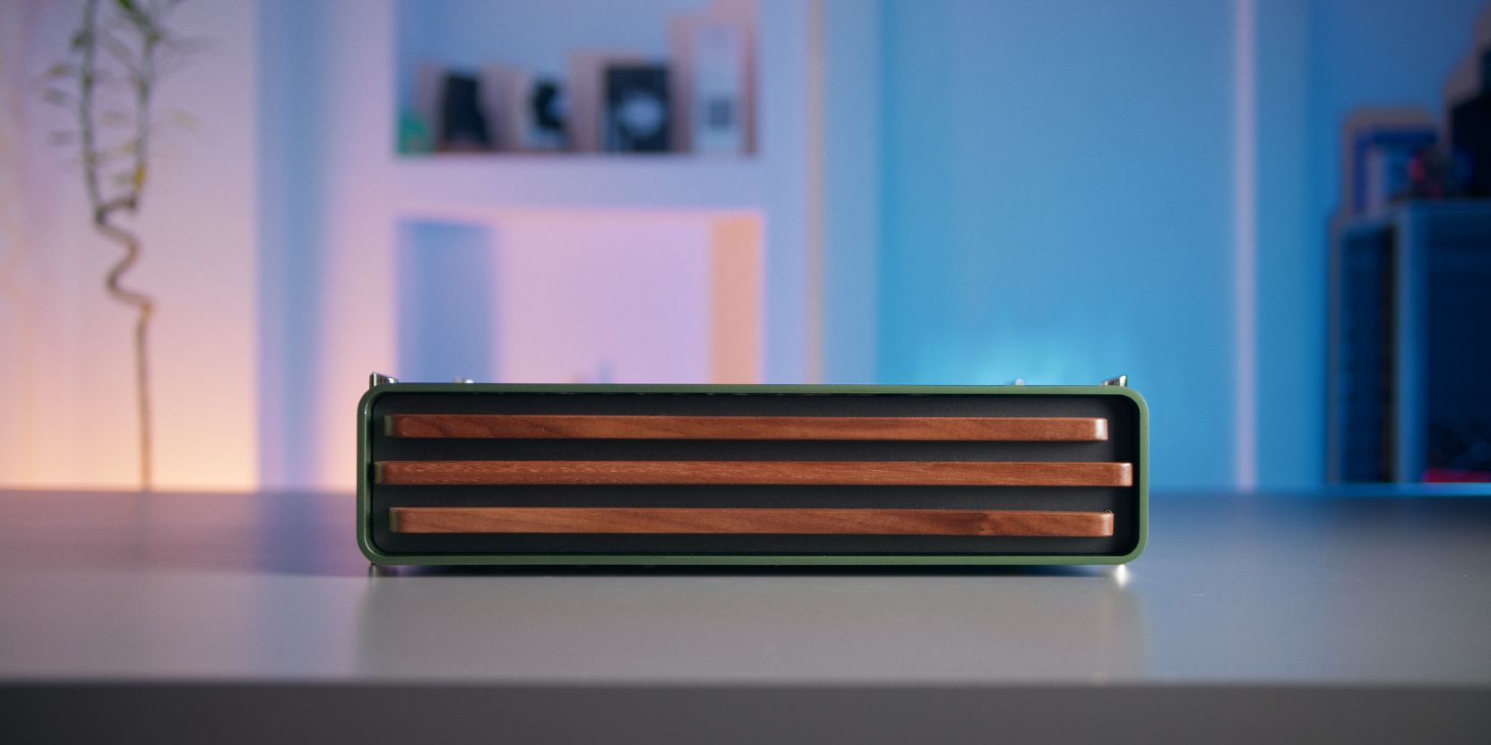
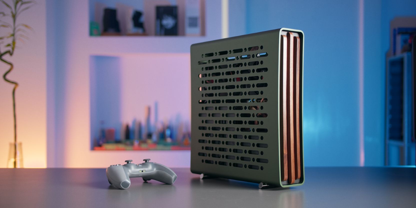
If you’re going to be using the TETRA in the horizontal mode, then you will need to do the same with the two remaining chrome stands on the opposite side of the case (you can skip the tape).
And with that, we’re done with assembly 🎉
If you’ve found any mistakes, inaccuracies or missing information, please contact me.
The next chapter will go over setup instructions for setting up a Bazzite installation.