Prep
Motherboard
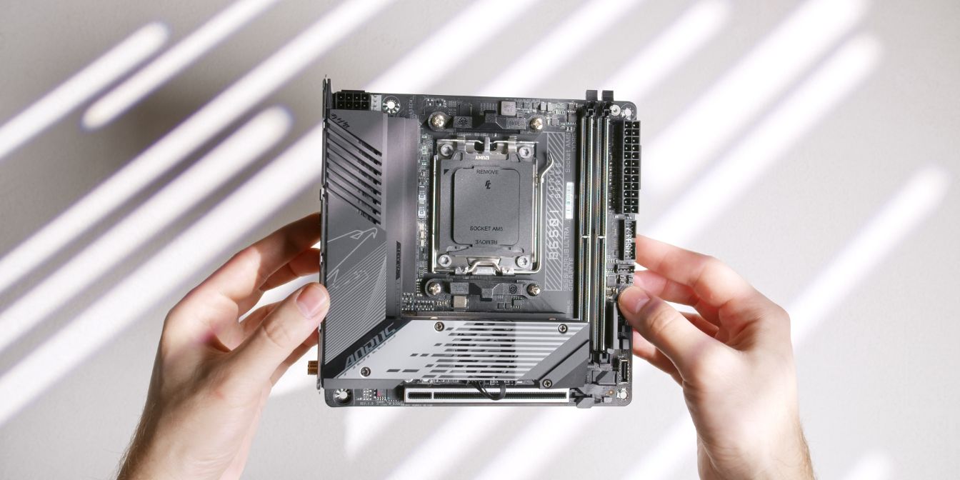
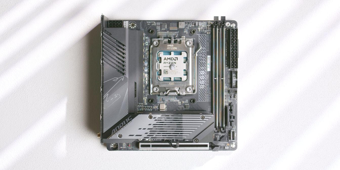
For the motherboard I’m using the B650i Aorus Ultra from Gigabyte.
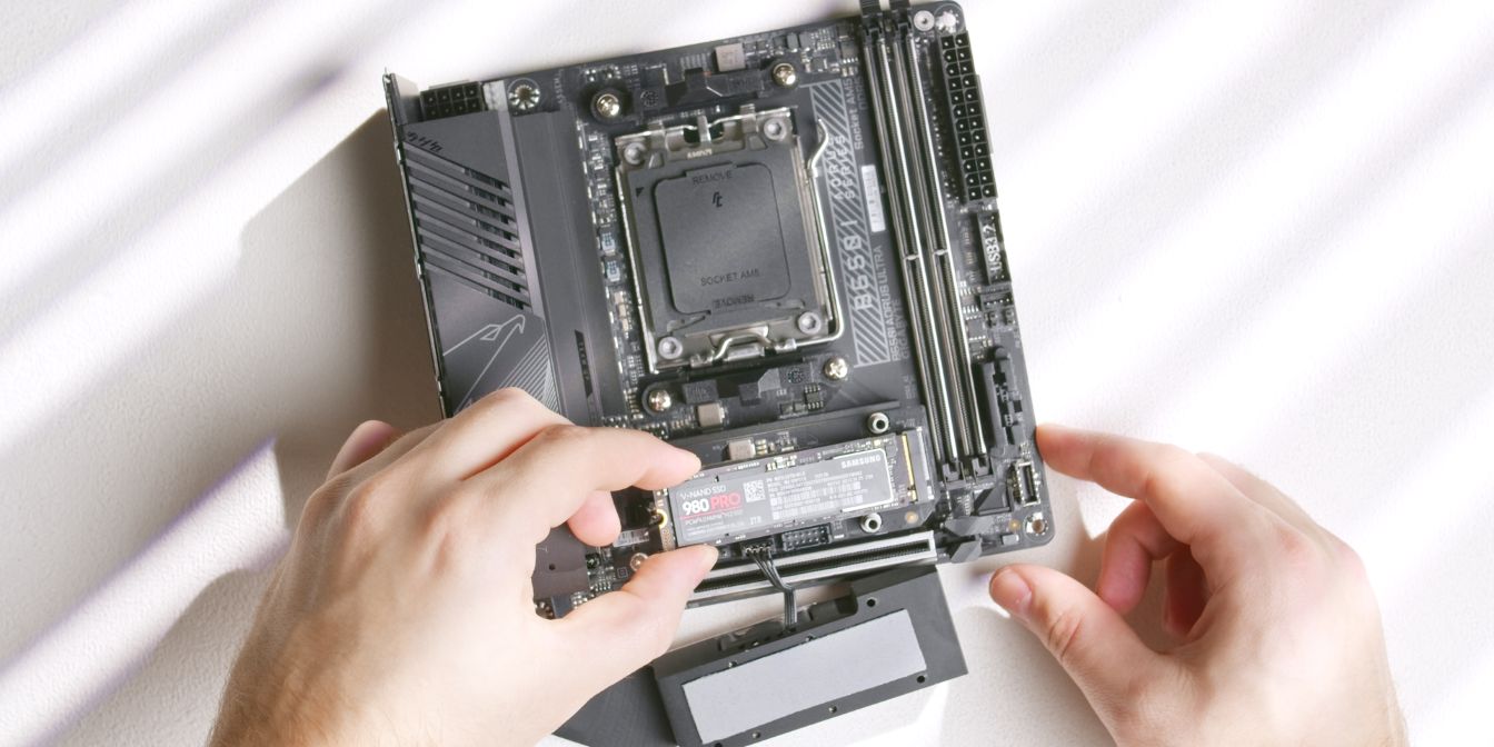
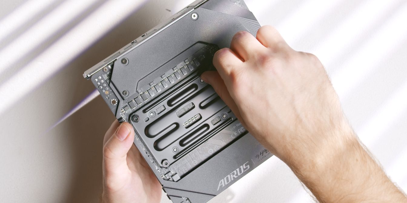
The B650i Aorus Ultra is one of the few AM5 motherboards that feature two front-side M.2 slots for fast NVME storage.
The second slot can be revealed by lifting up the first slot daughterboard PCB.
Don’t forget to peel off the protective plastic layer off from the pre-applied thermal pad that goes over the top of the drive. You can leave the thermal pad underneath the drive as is, unless you’re using a drive with memory chips on both sides.
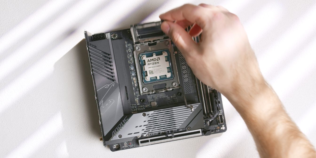
Slot in the AMD Ryzen 5 9600X CPU into the AM5 slot.
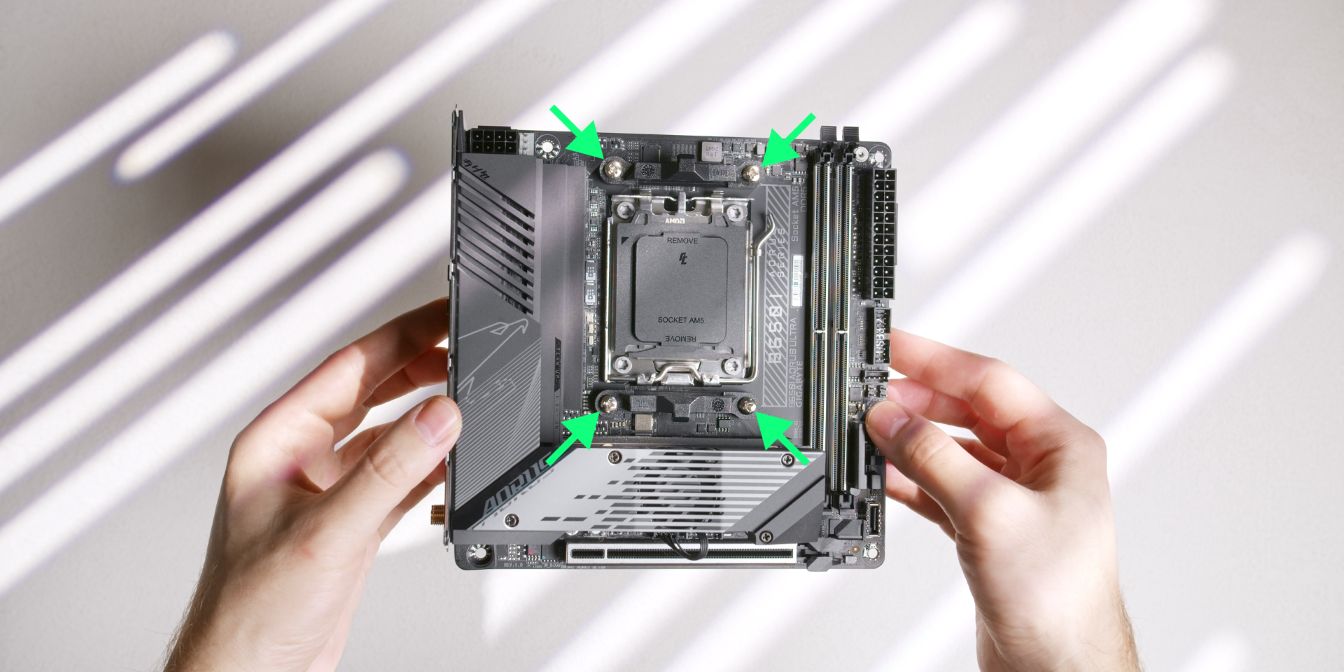
Remove the stock AM5 CPU mounting brackets by unscrewing the four Philips head screws. Place these in your motherboard box for safekeeping.
CPU Cooler
We will be using optional offset brackets from DingKey Designs to squeeze every ounce of performance out of the Thermalright AXP90-X36 cooler.
They work by offsetting the cooler downwards so that the center of the coldplate sits directly over the hottest part of the CPU. See this video from Noctua explaining why this works on AM5 CPUs.
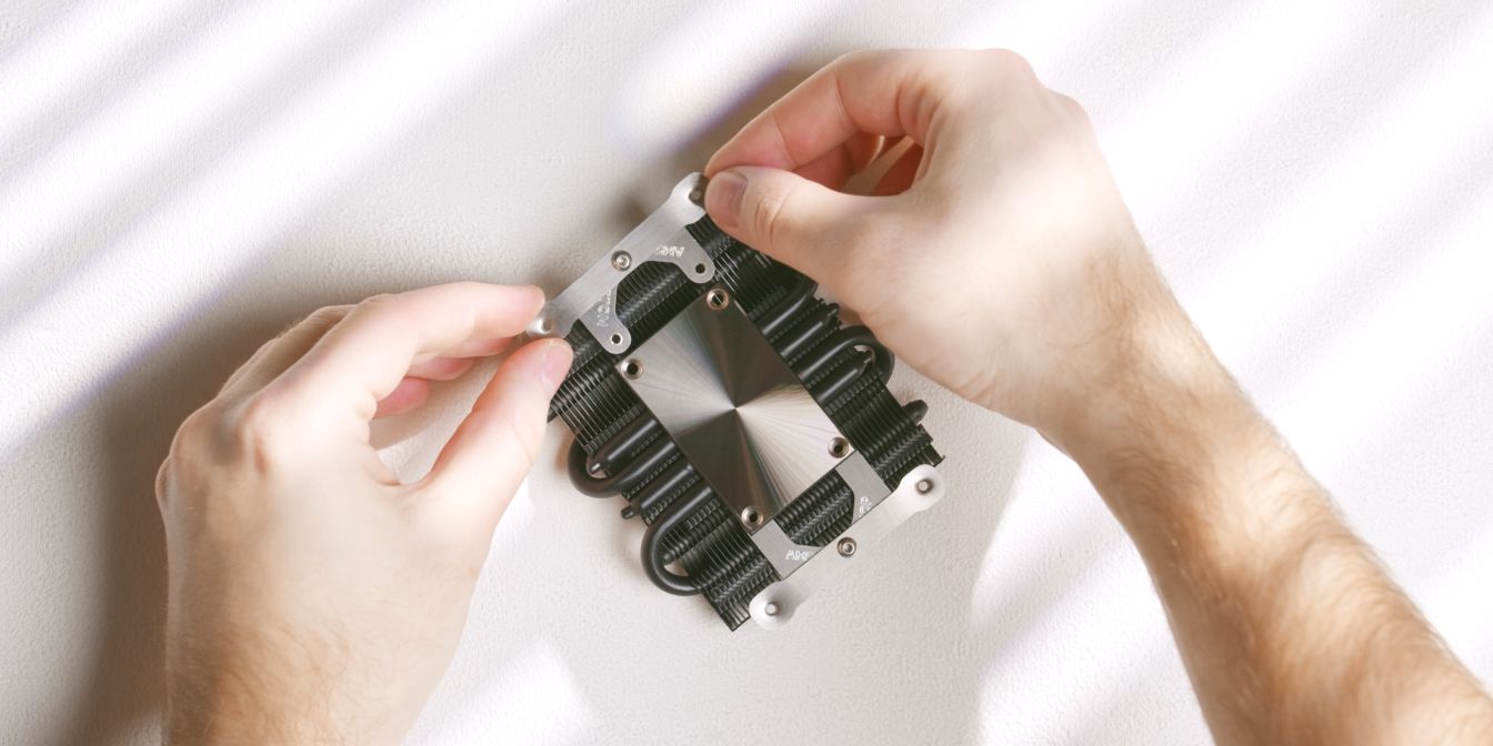
Use the original mounting screws to secure the two brackets to the cooler. Bracket orientation doesn’t matter for now, but make a mental note that one of the brackets is longer (marked with “TOP”).
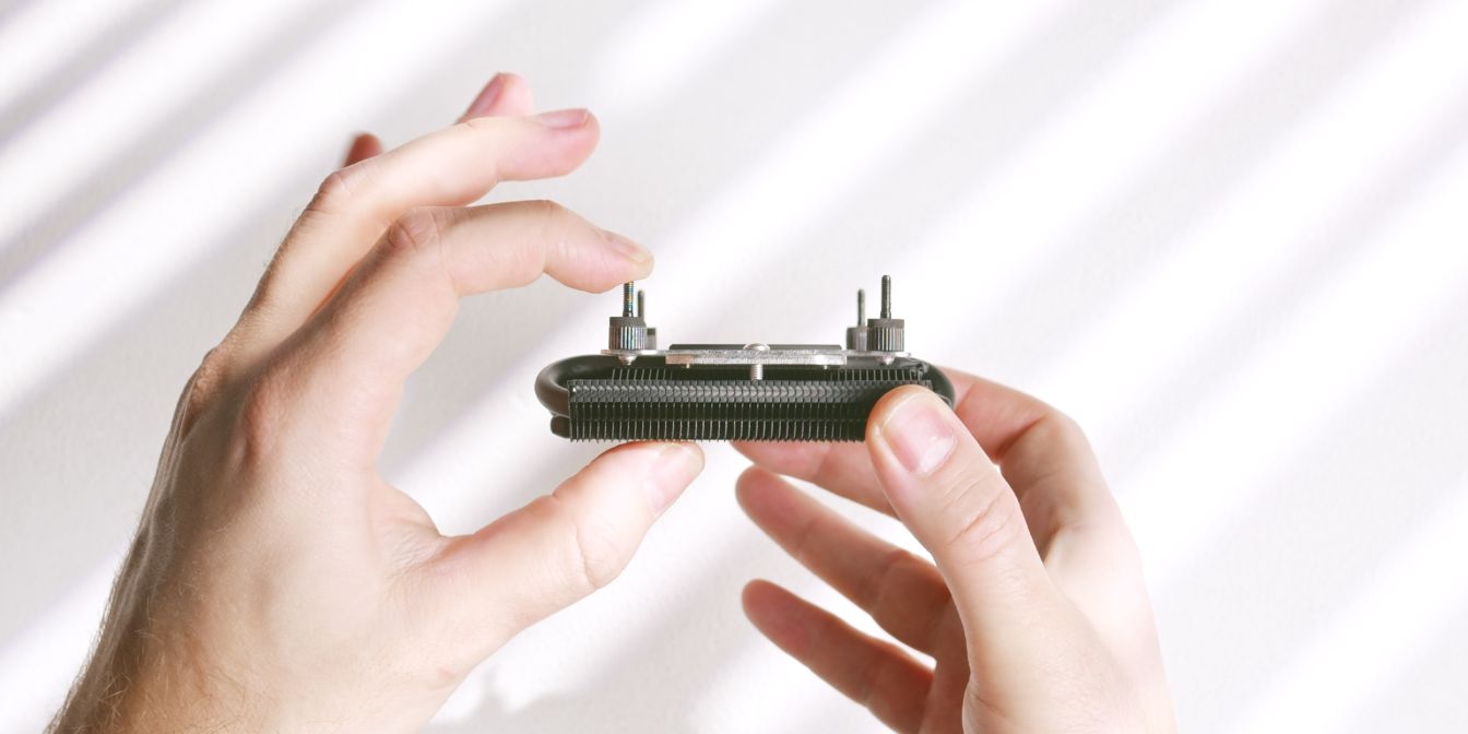
The AXP90-X36 comes with two sets of mounting screws, we need to use the shorter ones to avoid the screws protruding on the opposite side of the motherboard.
For consistency, I apply a pea sized drop of TG Duronaut (affiliate) onto the CPU. A more uniform method would be to use a cross patern but I find I’m less consistent with that method between applications.
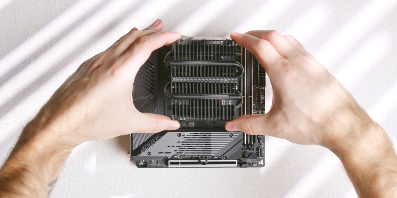
Place the heatsink onto the CPU with the longer offset bracket towards the north (up) part of the motherboard.
Make sure that the screws are aligned with the AM5 backplate threaded posts and feed them through simultaneously, keeping the heatsink level.
Flip the assembly around, holding the heatsink against the motherboard.
Hand tighten the included nuts onto the screws just enough so that the cooler won’t come off.
Continue tightening the nuts using the included thumb screw tool.
This will be easy to see on the motherboard’s north side, but very difficult on the opposite side as the leaf spring will be obstructed by the NVME heatsink.
I tend to go by feel here, going for an even tightness across all four nuts.
You can also look at how much each screw is protruding inside the nuts and have them all sit at about the same depth, although keep in mind that screw length may vary.
CPU Fan
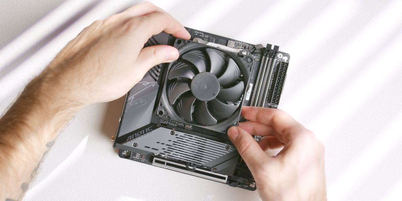
Install the fan included with the Thermalright AXP90-X36 onto the cooler heatsink using the stock fan clips.
RAM
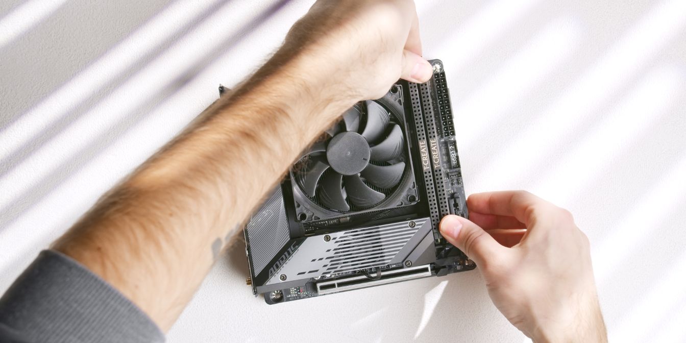
For RAM I’m using a 32GB 6000Mhz CL30 kit from TEAMGROUP, but given the current RAM prices I cannot recommend spending a lot on RAM.
My recommendation would be to find the cheapest available 16GB DDR5 kit that fits in the Midori (height ≤ 38mm for revision 2.4).
GPU Shroud
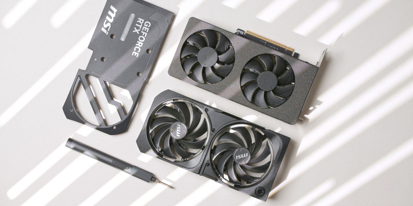
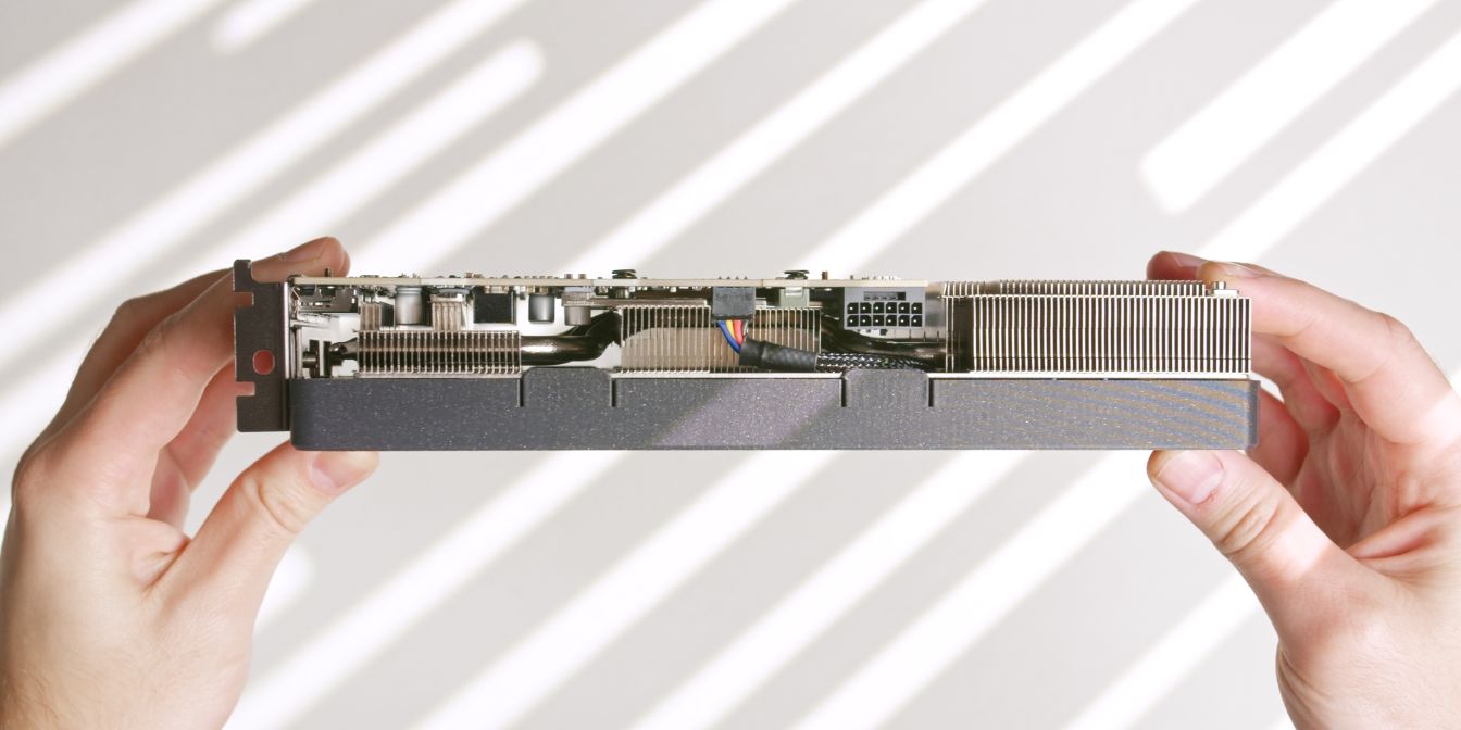
For this build I’m using the MSI RTX 5070 Shadow 2X.
The Ventus 2X (affiliate link) is also viable, as it seems to be functionally identical to the Shadow 2X.
To fit it inside the Midori, we will need to de-shroud the card and use 90mm Noctua slim fans instead. Thankfully, this procedure is super simple, just a couple of screws, no tamper seals or thermal pads need to be removed.
For a clean look, I designed a custom 3D printed replacement shroud, but zip-ties can also be used for holding the Noctua fans onto the heatsink.
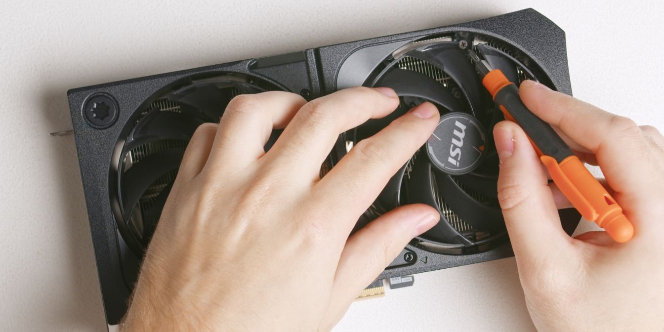
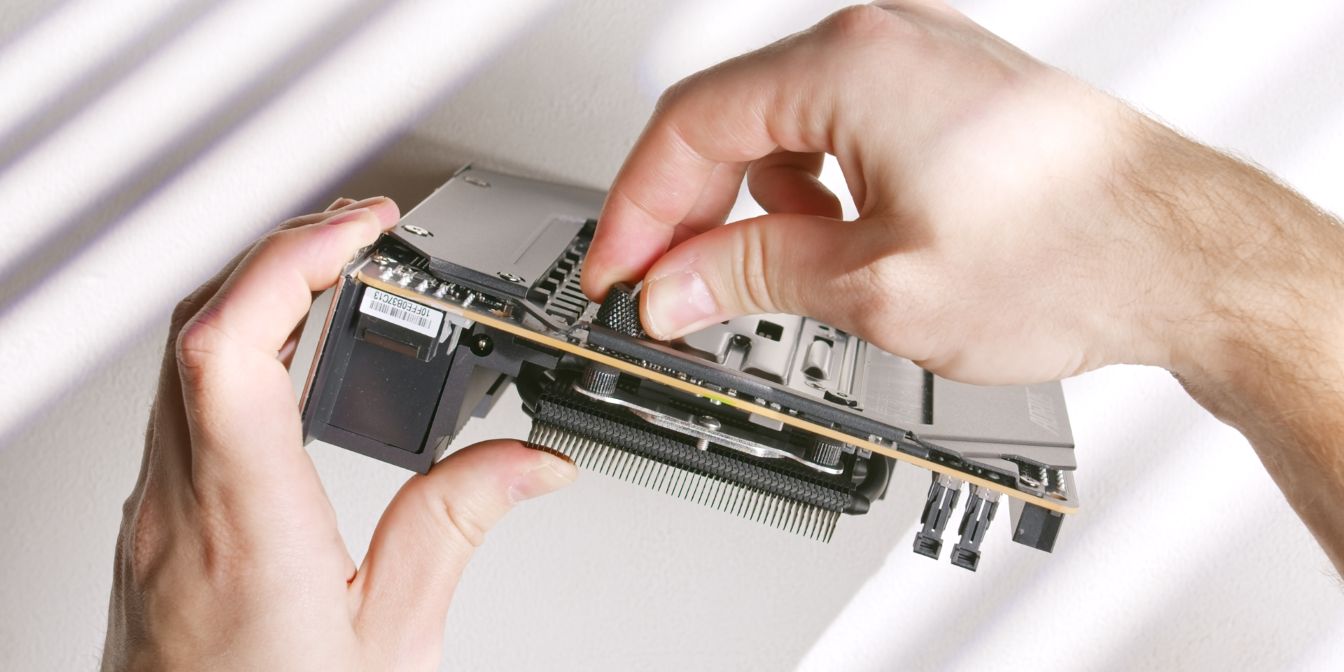
The top shroud is held in place with just four Philips-head screws hidden underneath the fan blades, two under each fan.
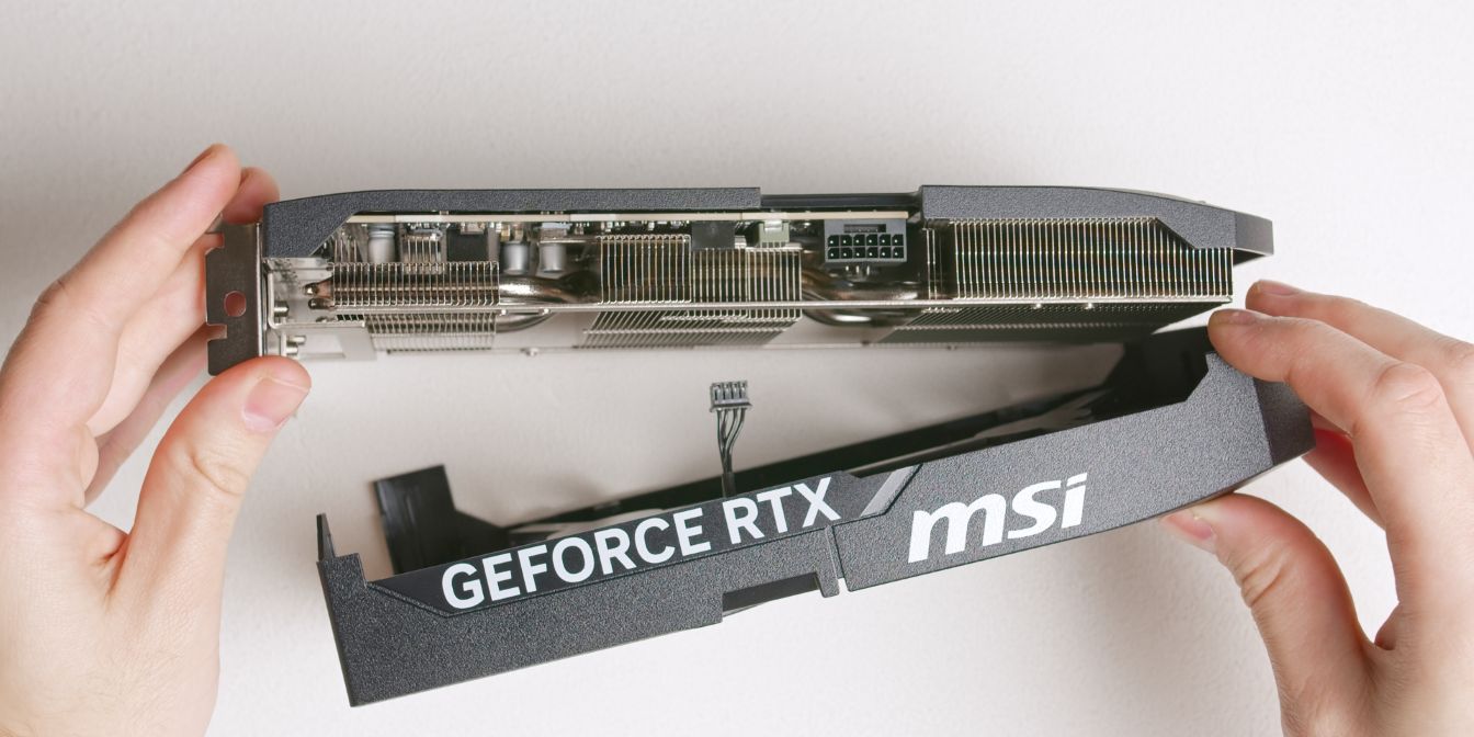
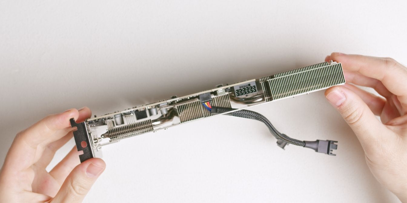
With the four screws removed, the top shroud piece can be lifted up.
Don’t forget to disconnect the mini 4 pin fan cable. Although not ideal, if you can’t get your fingers in there to grab the connector, an upwards tug does the trick.
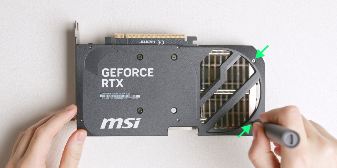
Let’s also remove the backplate, which is held in place by few more screws.
Two screws are on the backplate itself, near the edge of the card…
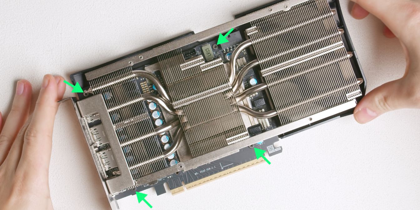
… and four more screws on the front of the PCB.
In my case, these screws seemed to be “captive” in the PCB, I didn’t want to risk damaging the PCB by trying to pry them out, so I just left them in there.
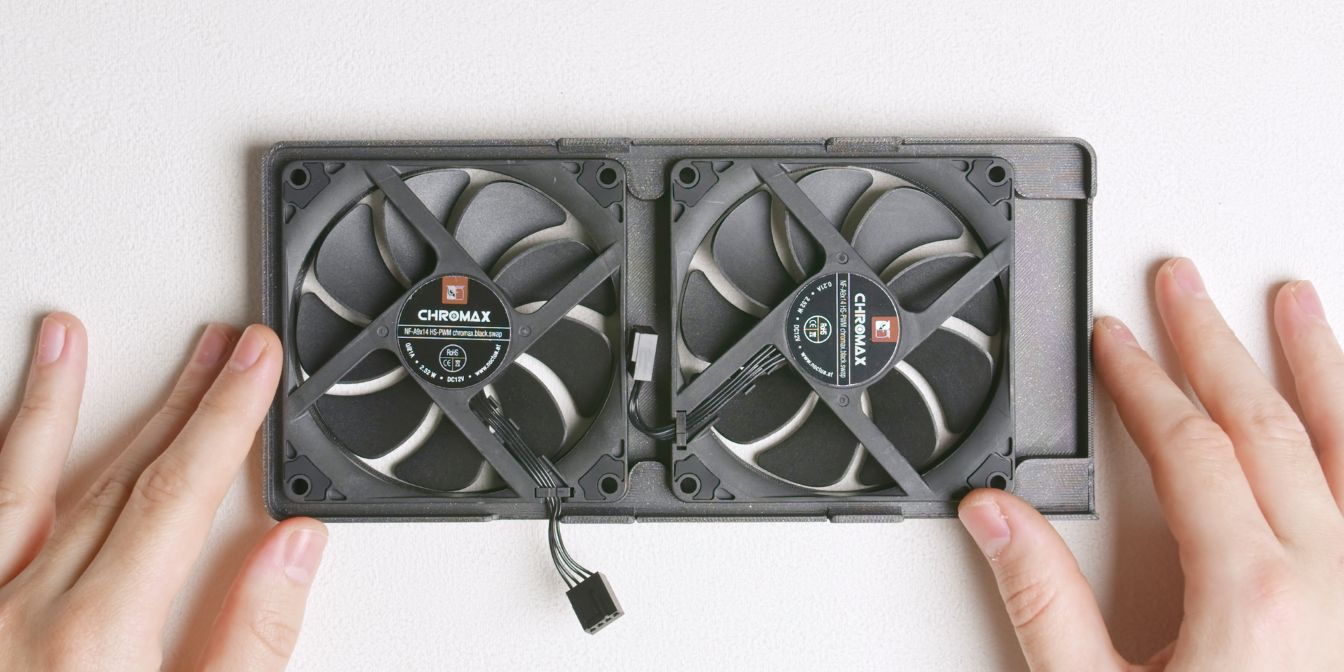
Insert the two Noctua NF-A9x14 fans inside the 3D printed shroud, with the outlet side facing up (the side with the sticker on the fan hub).
Have the leftmost fan oriented as shown, with the 4pin fan connector hanging outside the shroud, and the other fan with the connector tucked inside.
The shroud is designed with a zero-gap between the fans and the heatsink for maximum cooling performance.
Connect the mini 4pin fan adapter cable to the GPU fan header.
I have a 15cm adapter cable from AliExpress, but an even shorter one would be ideal here. This 10cm one from Amazon (affiliate) should fit even better.
Alternatively, if you don’t have a cable like this, you can hook up the two Noctua fans to a 4 pin PWM header on your motherboard (with a Y-splitter cable) and then control them through software via FanControl.
Connect one end of the adapter cable to the fan with the 4 pin connector facing inside the shroud and leave the other disconnected for now.
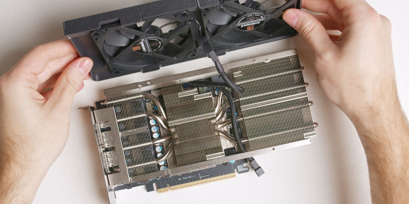
Carefully place the shroud onto the heatsink, making sure the cable folds inside the space between the two heatsink fin stacks on the GPU.
Lastly, connect the other fan connector to the adapter from outside the shroud.
Press down on the shroud, making sure all four clips (two on each side) are latched securely onto the heatsink rail.