Assembly
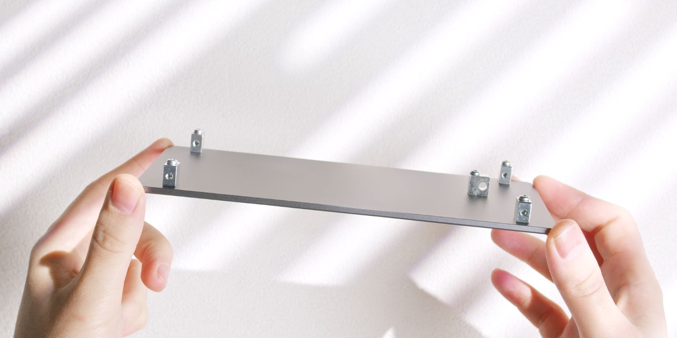
Spine
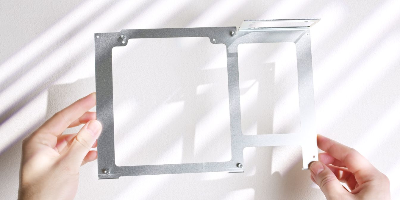
Let’s start with the center spine of the case, where we need to add four motherboard standoffs / spacers.
The Midori uses a numbering system for the included mounting hardware, I’ll be referencing these part numbers as well throughout this guide.
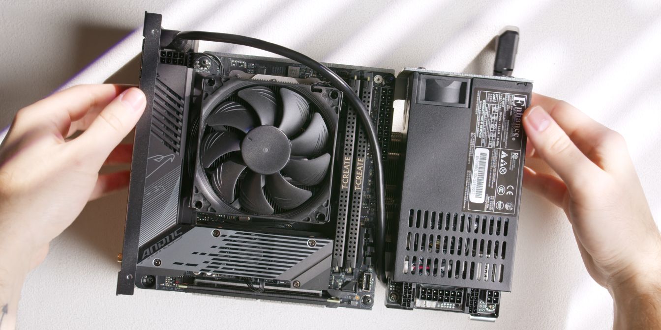
Motherboard
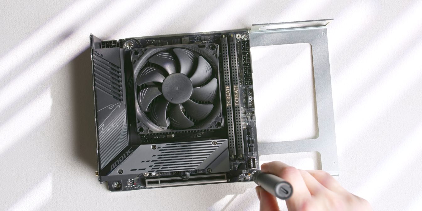
Secure the prepped motherboard onto the four standoffs added in the previous step.
Rear panel
For installing the rear panel we’ll need the following mounting hardware:
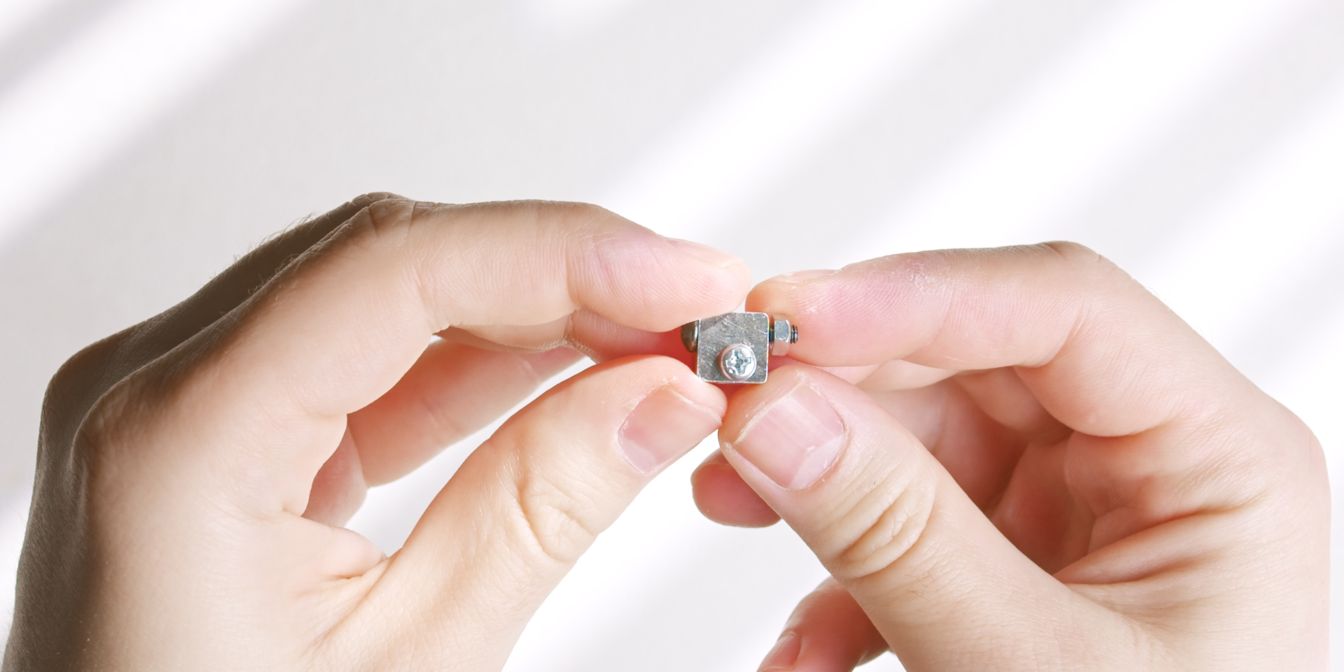
The Midori makes use of these quirky connector blocks throughout its assembly.
Take one of the blocks that have a hole on the wider face and secure it to the spine with the shorter screw (9).
Insert the longer screw (18) through the rear panel and the pass-through hole of the connector block, into an M3 nut (20) on the opposite end.
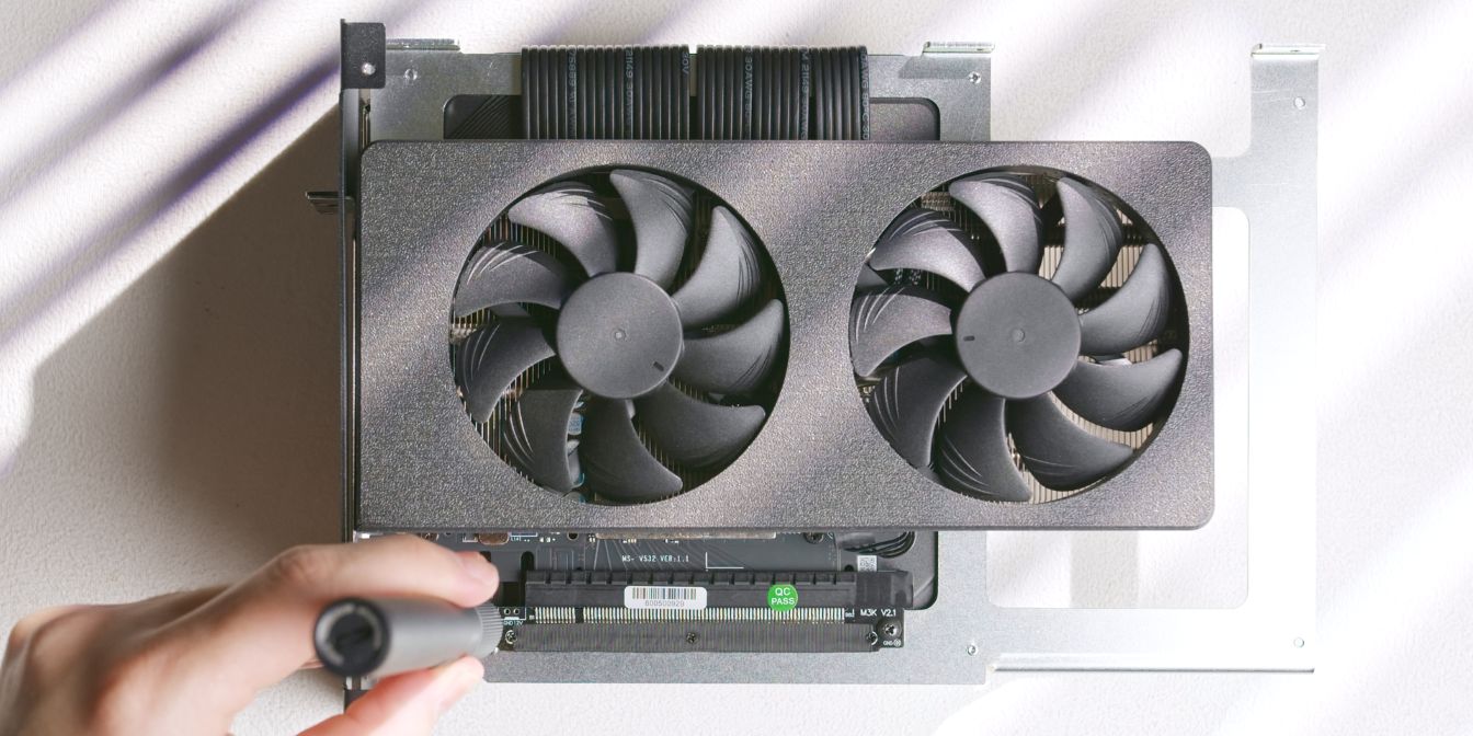
GPU
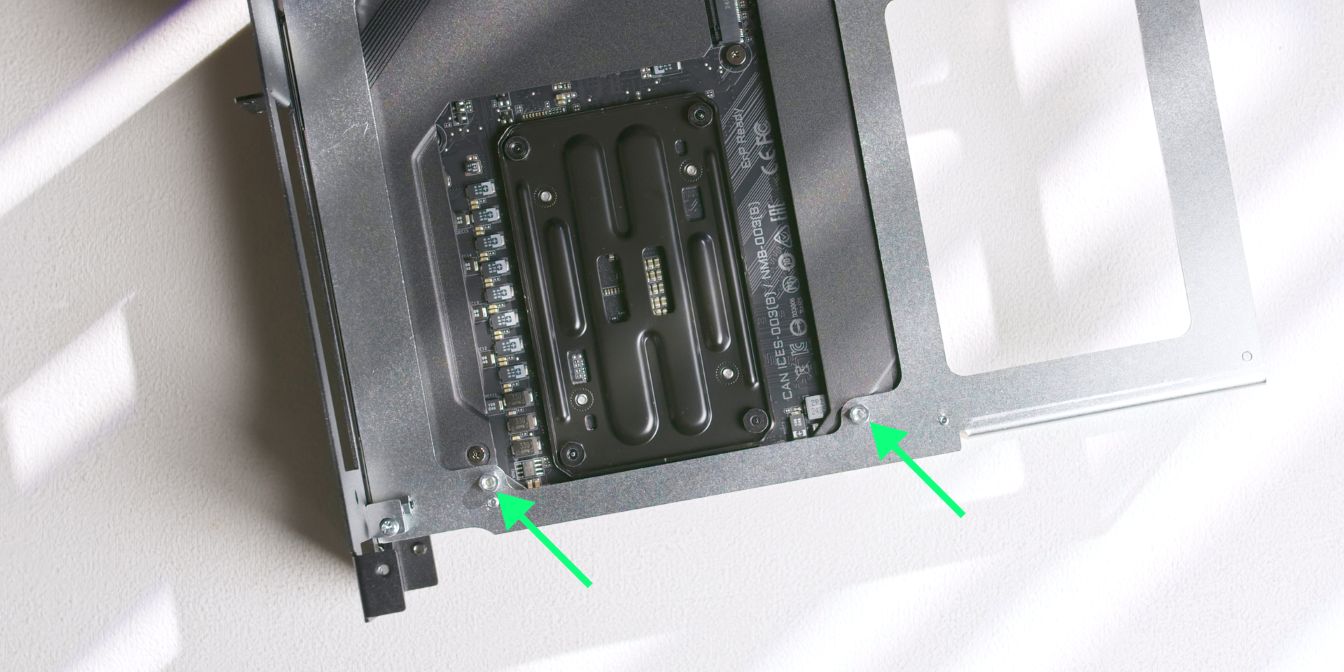
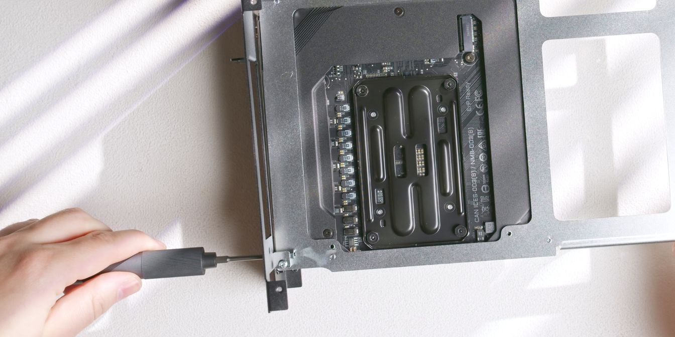
Add two standoffs / spacers on the backside of the spine.
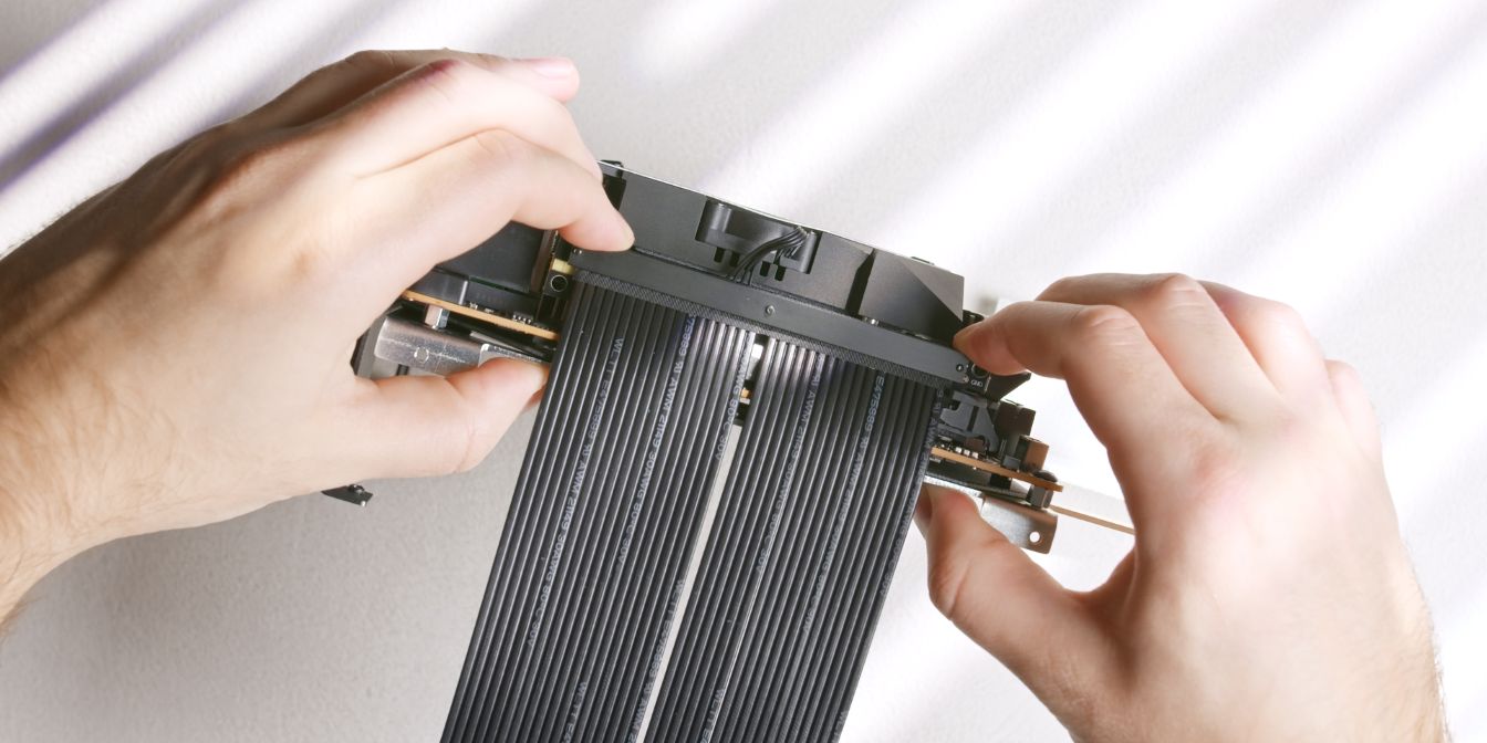
Insert the GPU riser cable into the motherboard PCIe slot.
Give the riser a bend along the edge where it folds over the spine. What worked best for me was “pinching” it between my thumb and index fingers. Just don’t overdo it.
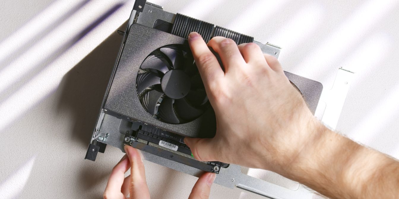
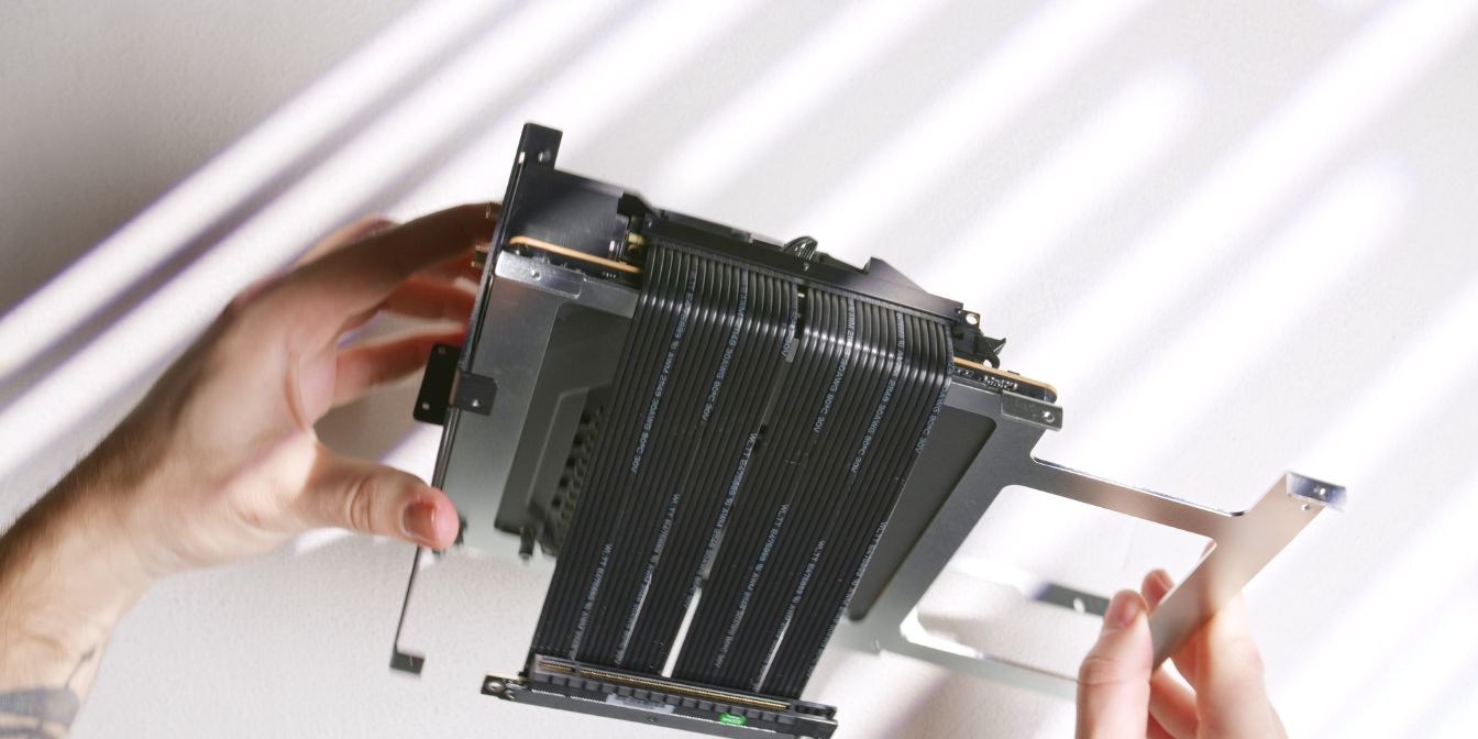
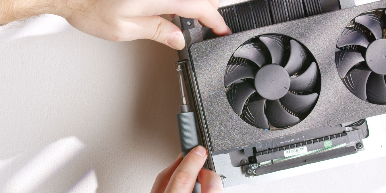
Add-in the de-shrouded GPU (see prep), making sure the I/O bracket goes through the rear panel cut-out, and then carefully slot in the GPU into the riser.
Since the riser is not yet secured to the spine, there’s some slack to work with when aligning it with the PCIe connector.
Secure the GPU riser onto the two standoffs we added previously.
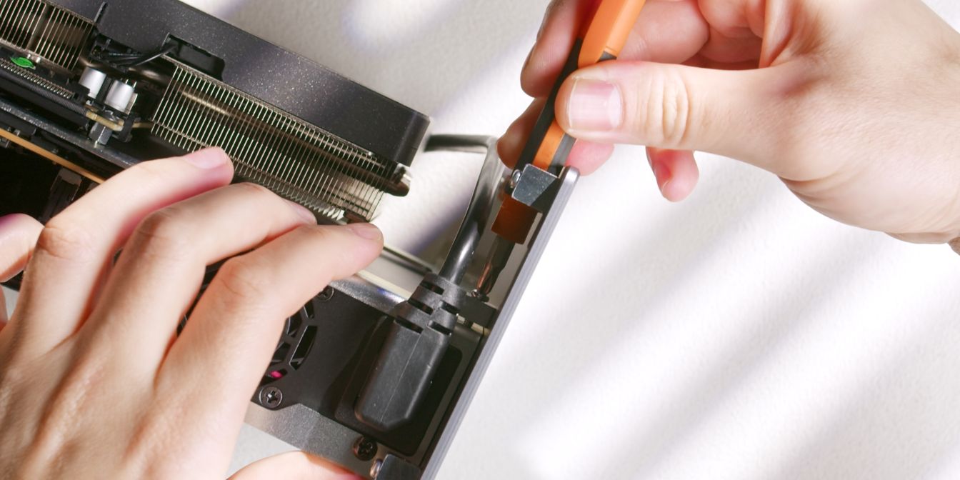
Secure the top of GPU I/O bracket to the rear panel with two screws (12).
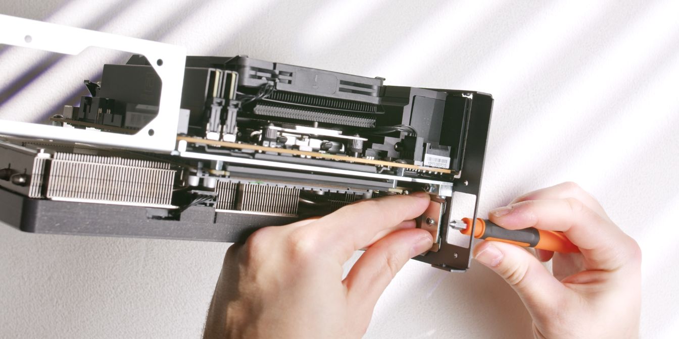
The bottom part of the GPU I/O bracket is clamped with a threaded plate, held in place with an M4 screw inserted through the rear panel.
See: No signal
PSU
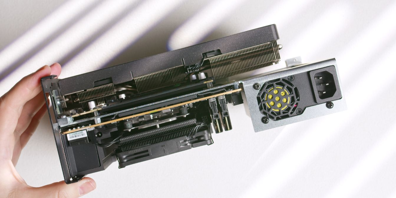
Secure the FlexATX power supply to the spine using the three included PSU screws (19).
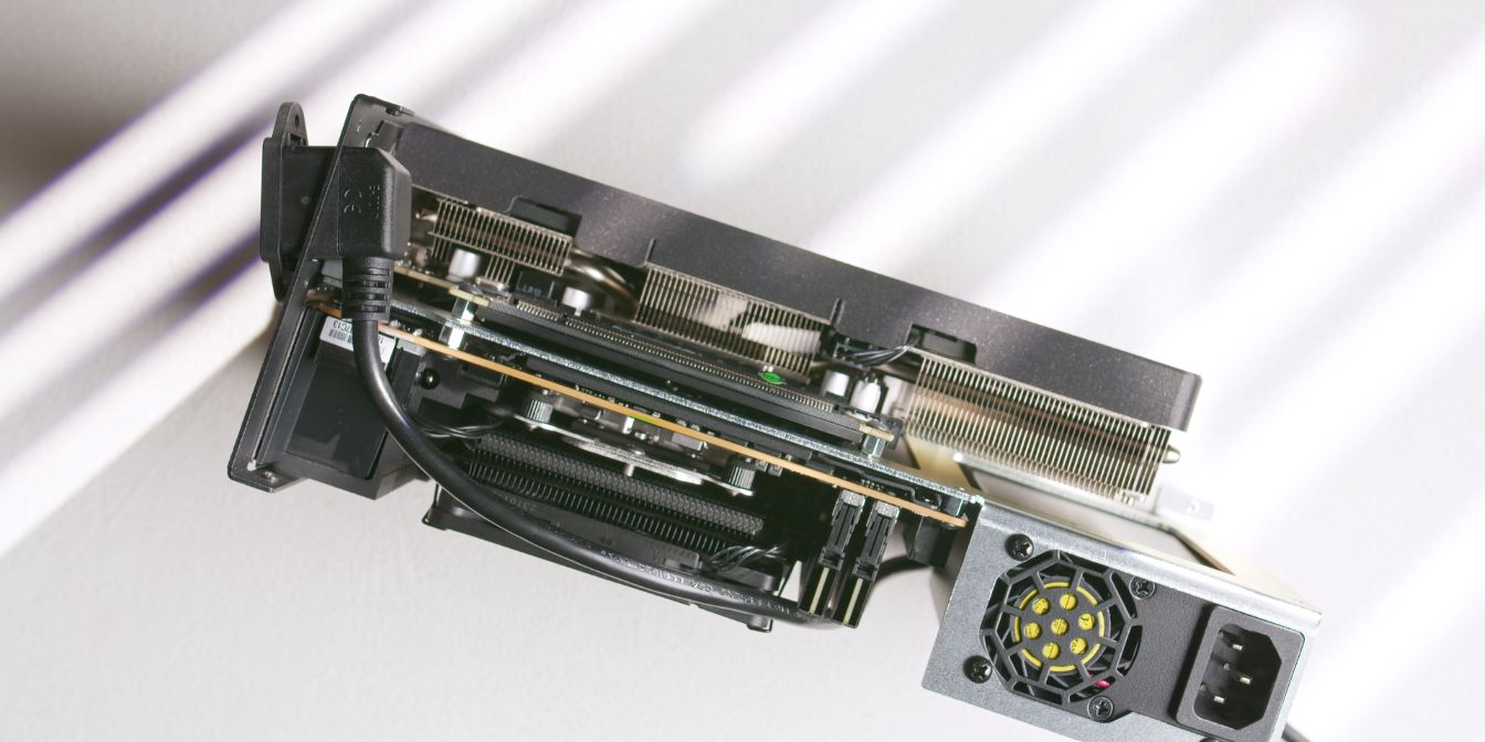
Feed the L-plug power cable through the rear panel cutout and secure the inlet plug with two countersunk head screws (16).
Route the power cable over the top side of the motherboard, then in-between the motherboard and PSU over to the GPU compartment.
Connect the power plug to the PSU power inlet.
Front Panel
Let’s prepare the front panel with the following mounting hardware:
One of the same type we used for the back panel (22) goes in the middle, and then the four remaining ones (21) get secured in each corner of the panel.
Secure the front panel to the spine by fitting a screw through the middle block.
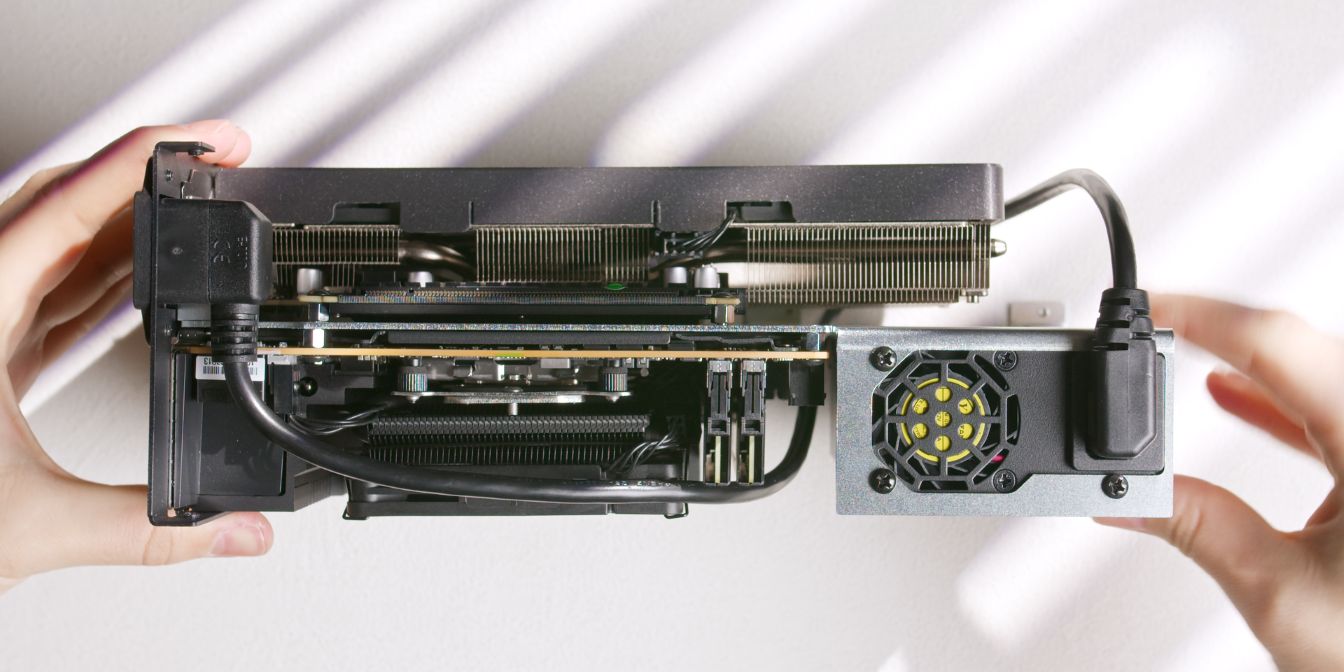
PSU Cables
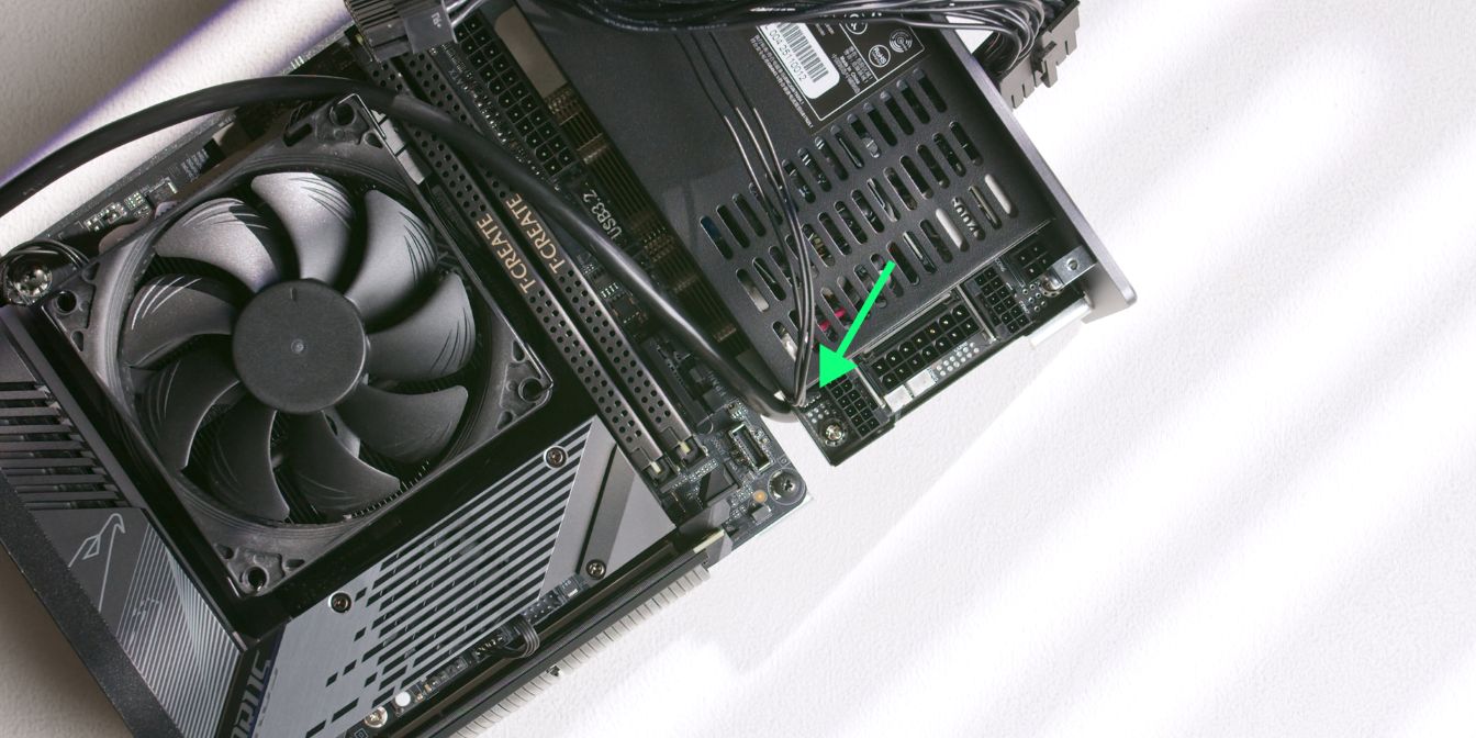
The ATX 24 pin cable of the ENP-7660L-OVT power supply includes a 3 pin sense header that needs to be connected to the power supply.
The CPU and GPU connectors are of the infamous 12V-2X6 variety. The use case does make sense, as we’re working with very limited space.
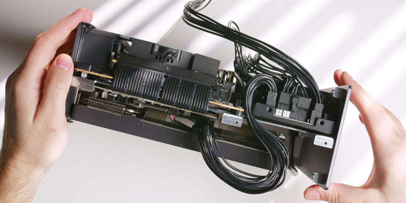
Plug in the 25cm 12V-2X6 GPU power cable and route it in between the motherboard and PSU, then plug it into the GPU.
Plug in the 18cm 14 pin plug end of the ATX 24 pin power cable, route the cable along the longer side of the PSU, then plug it into the motherboard.
Finally, connect the 40cm CPU power cable and route it alongside the motherboard cable, then over the top side of the motherboard.
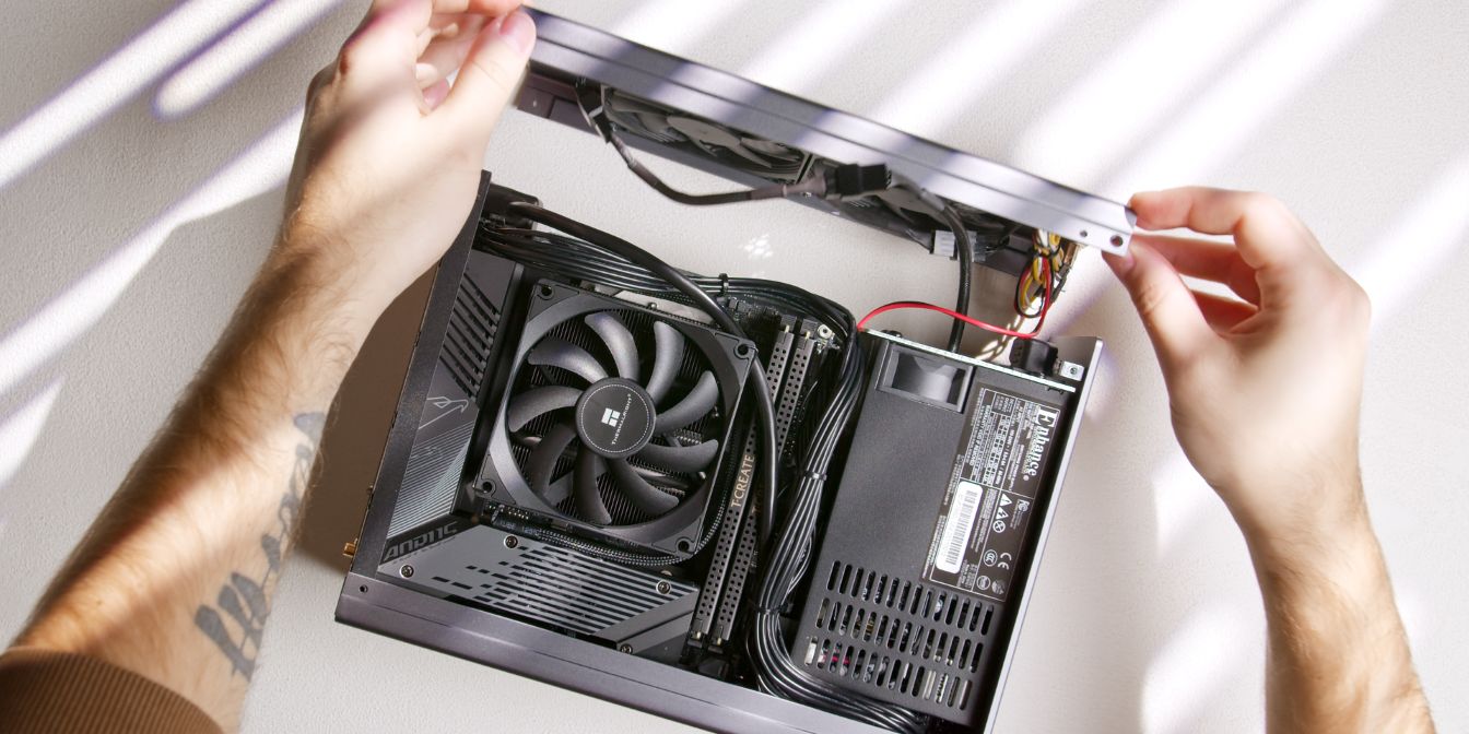
Bottom Panel
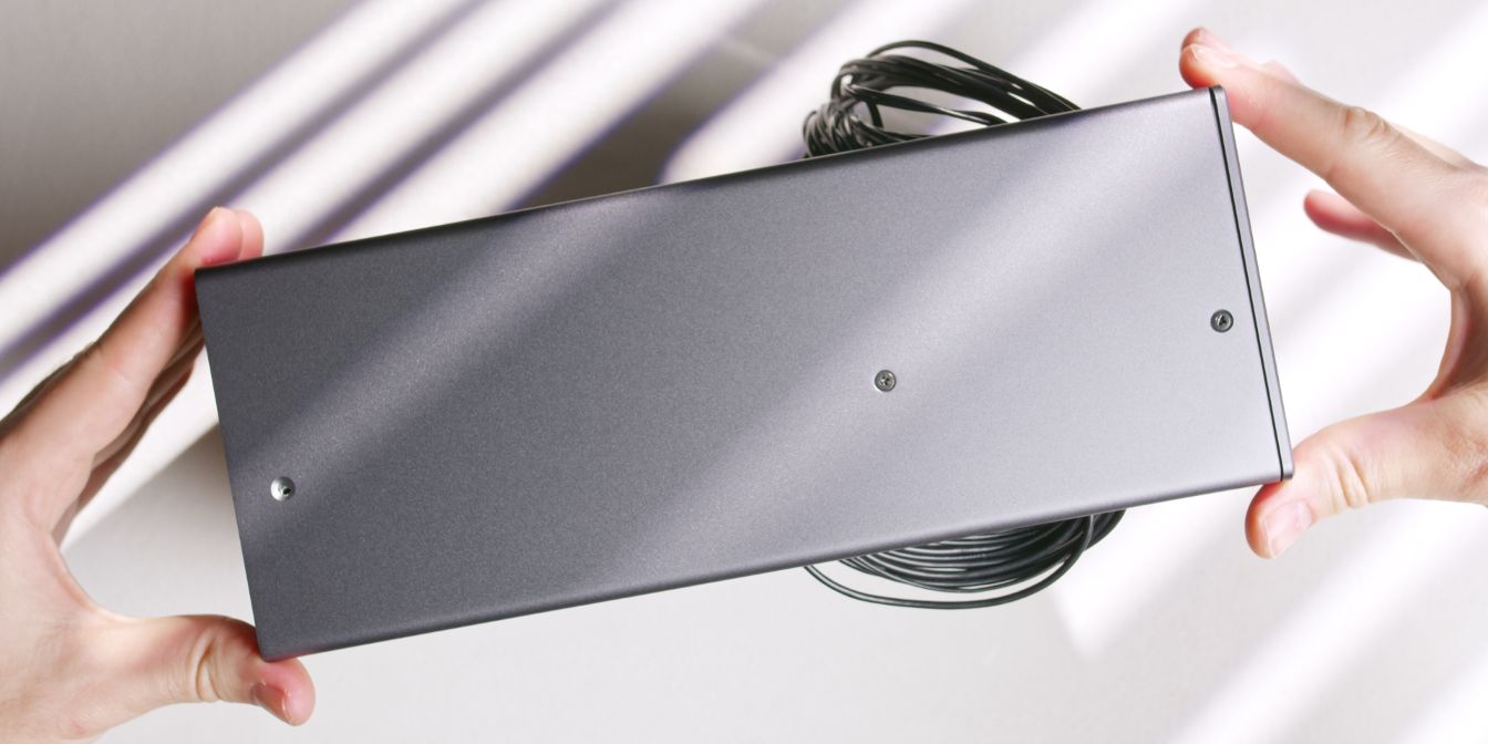
Place the bottom panel onto the case, lining up the holes on the rear and front panel.
Secure it with three countersunk screws onto the spine.
For reasons I could not determine, the hole closest to the rear panel did not align properly, so I ended up skipping it.
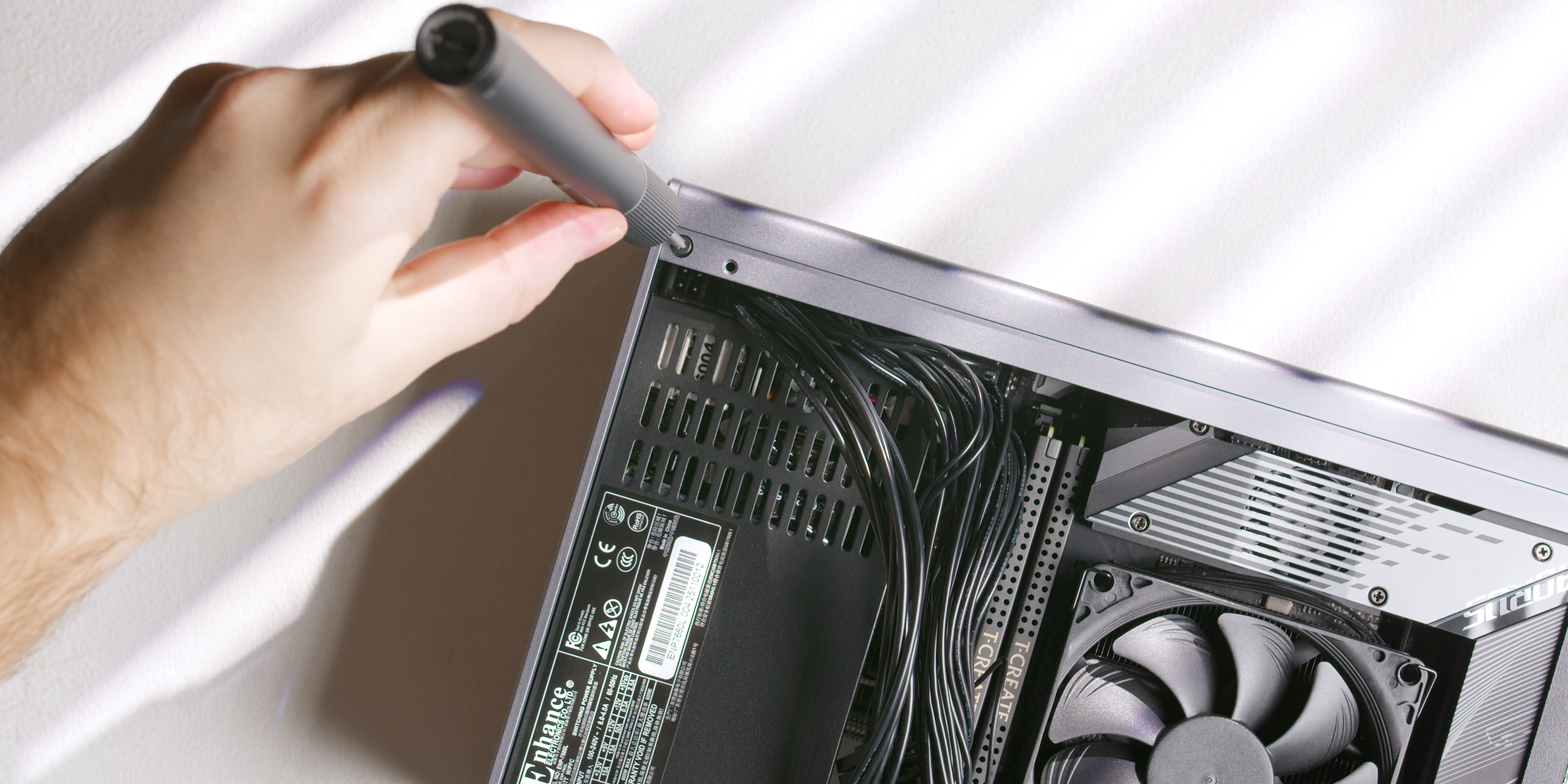
Secure the top panel to the front panel with one countersunk head screw (16) on each side of the case.
Exhaust Fans
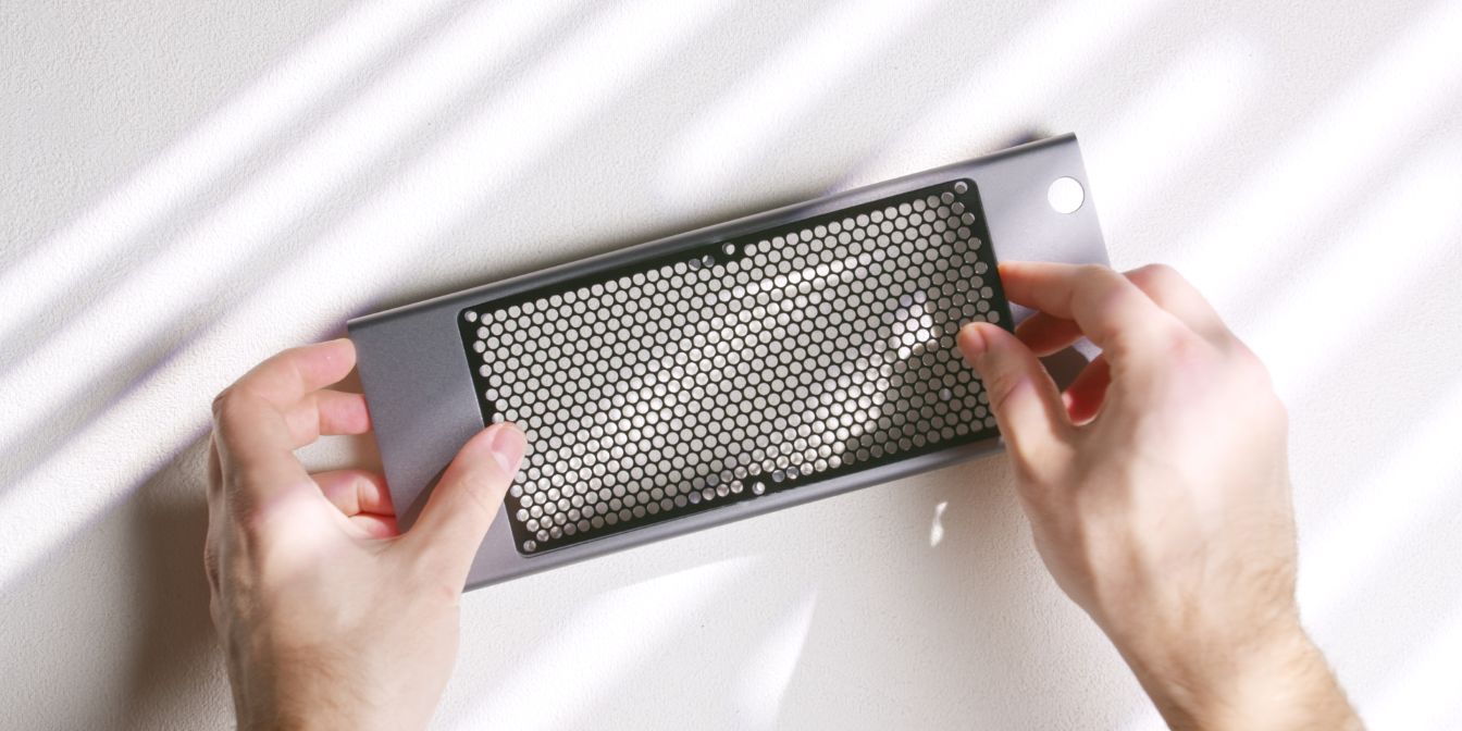
Place the fan grill over the cutout in the top panel.
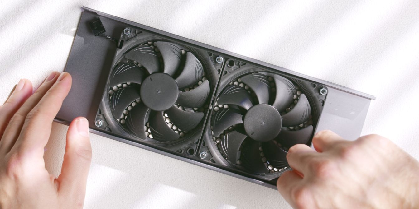
Align the two Noctua NF-A9x14 fans with the holes of the top grill.
Note the orientation of the fans, with the inlet side facing away from the grill.
Secure both fans to the top panel using six M3x20 screws (16) and six M3 nuts (20).
Exhaust fans in the Midori are only secured in three points, so note the placement of the two holes closest to the middle of the fan grill.
Power Button
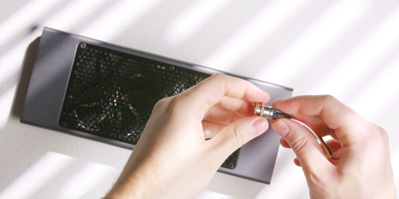
Remove the locking ring from the anti-vandal power button included with the Midori.
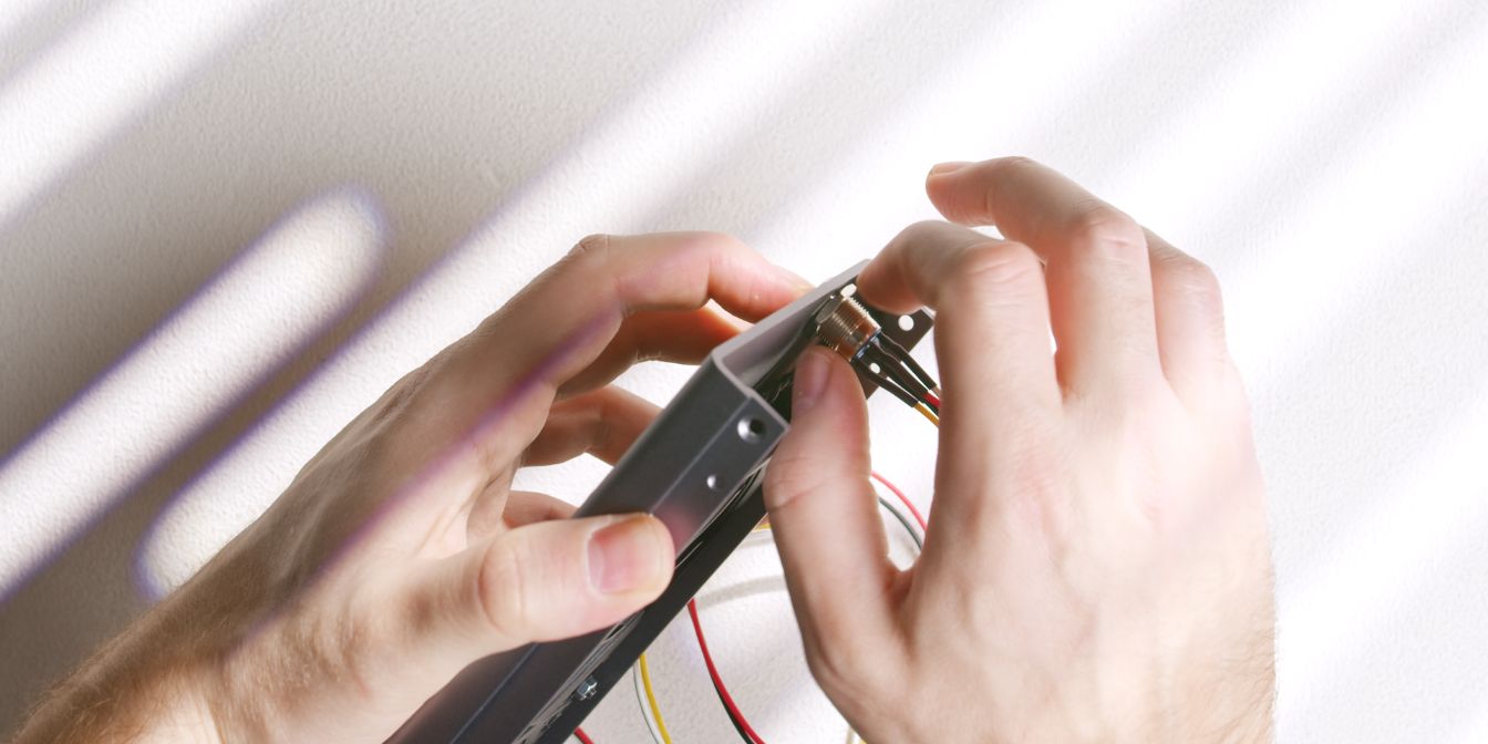
Insert the power button into the top panel cutout by feeding the cables through.
Add back the locking ring and thread it onto the power button. Finger tight should be good enough to prevent it from coming loose.
Cables
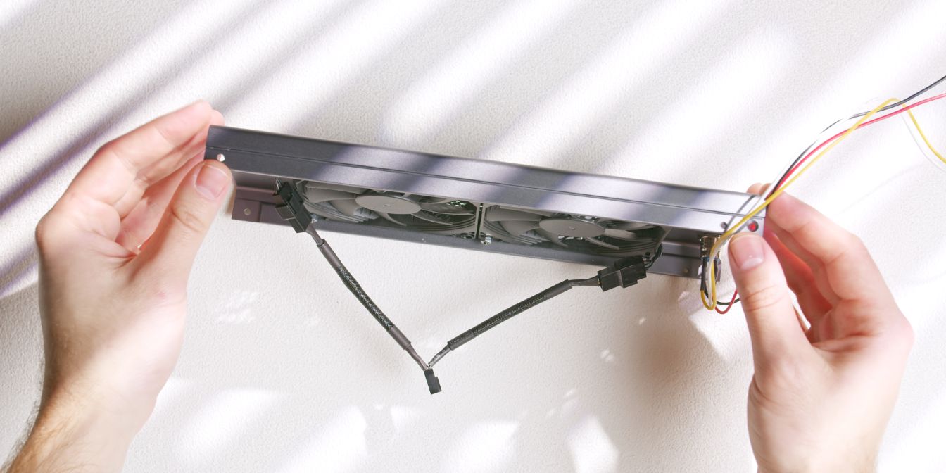
Add a 4 pin y-splitter cable in between the two top exhaust fans.
Route a 30cm fan extension cable from the motherboard over to the GPU side.
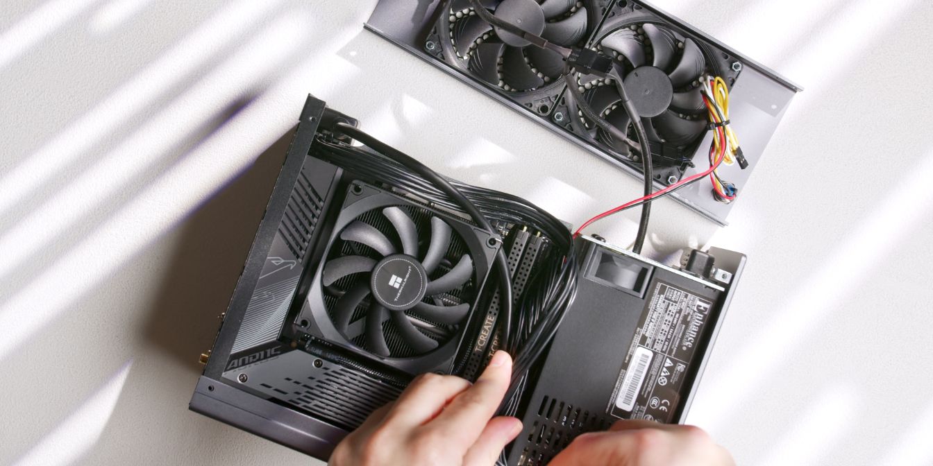
Place the case on its side, with the prepped top panel towards the top.
Connect the fan extension cable to the fan y-splitter cable.
Connect the white and yellow cable to the power button pins on your motherboard.
The red and black cable should be connected to the power LED pins if your motherboard has a full F_PANEL header.
Since the Gigabyte B650I AORUS Ultra uses a modular daughterboard PCB for the full F_PANEL header I chose to only use the power button functionality by connecting the white and yellow connector to the PWR_BTN header on the motherboard.
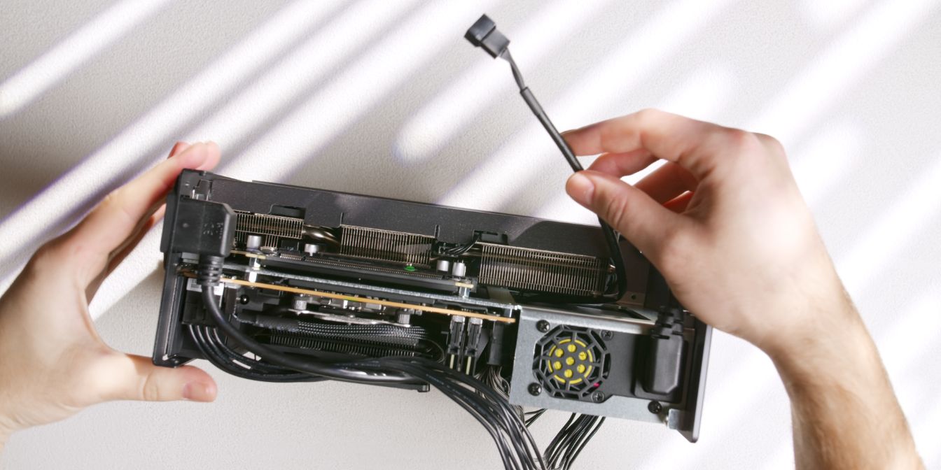
Use zip ties to hold the cables together and cable manage them in such a way that they won’t be pushing against the exhaust fan blades or the case side panels.
Align the top panel with the front and rear panel and fit it over the case, checking for any cables that might get pinched.
Secure the top panel with two countersunk (16) screws, one on each side of the case.
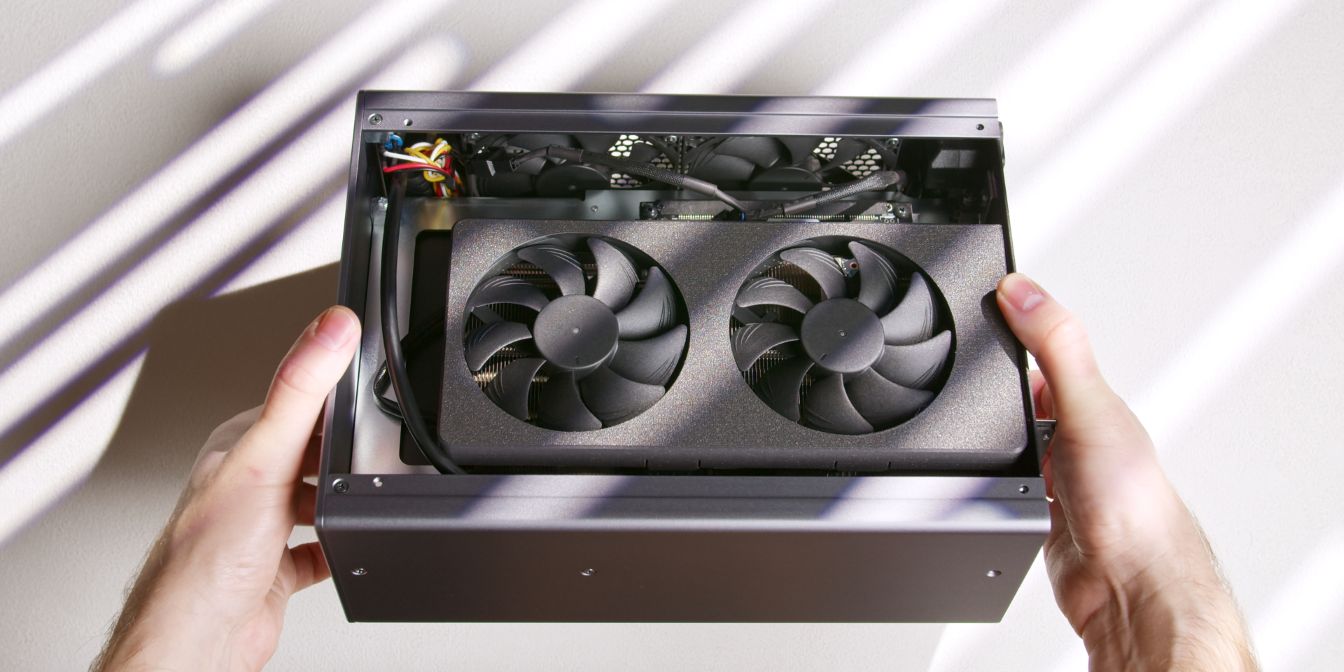
Double check if any cables are preventing the fan blades from spinning freely. You can do this by giving the fans a quick spin with your fingers.
If the fans are not spinning freely, double check your cable management. Likely culprits: CPU power cable, power/LED button cables, fan y-splitter cable.
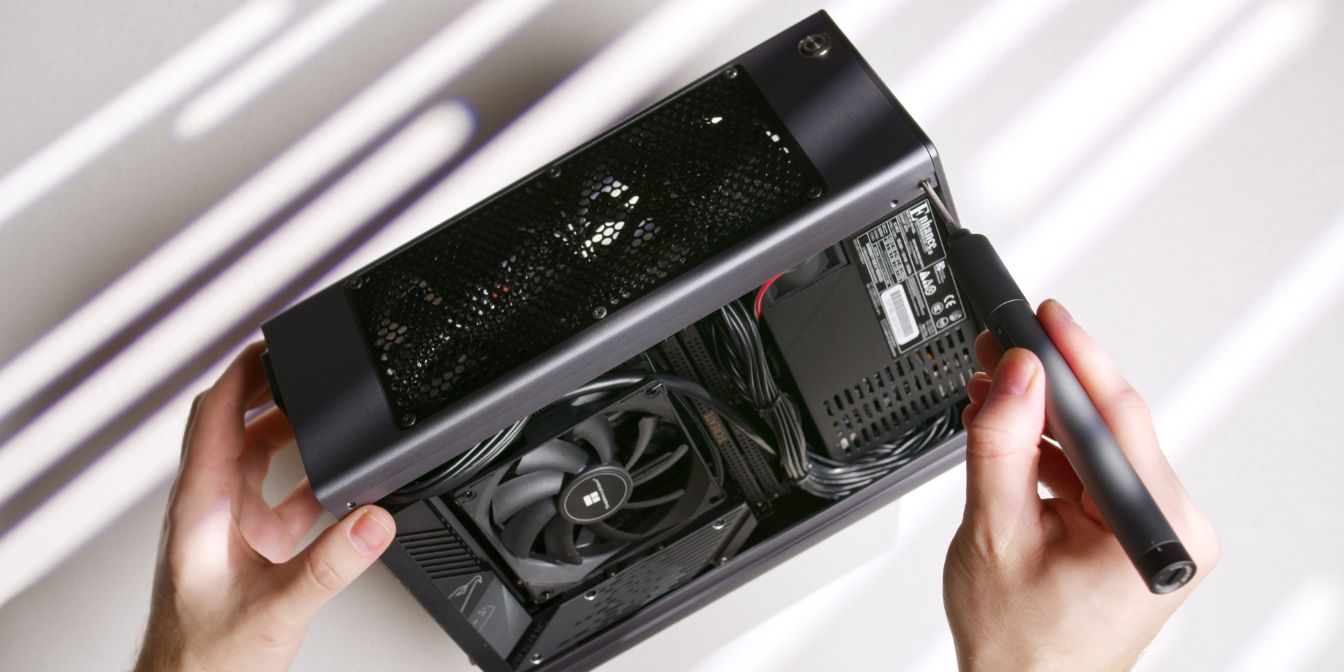
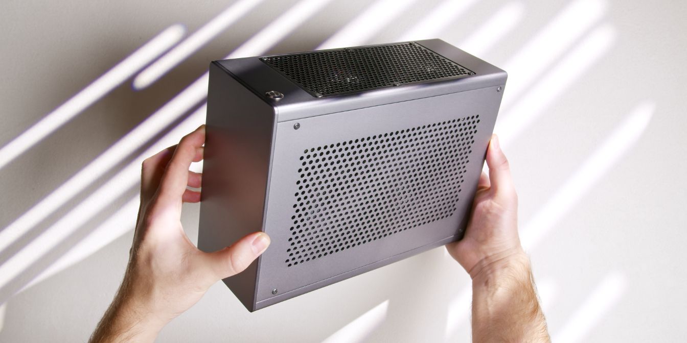
Side Panels
Secure the side panels onto the case with four countersunk head screws (17) on each side of the case.
If your side panels are bulging, check for any cables pushing against them. The side panels are slightly curved due to manufacturing, take advantage of their slight curvature by swapping the panels around and checking if fitment improves.
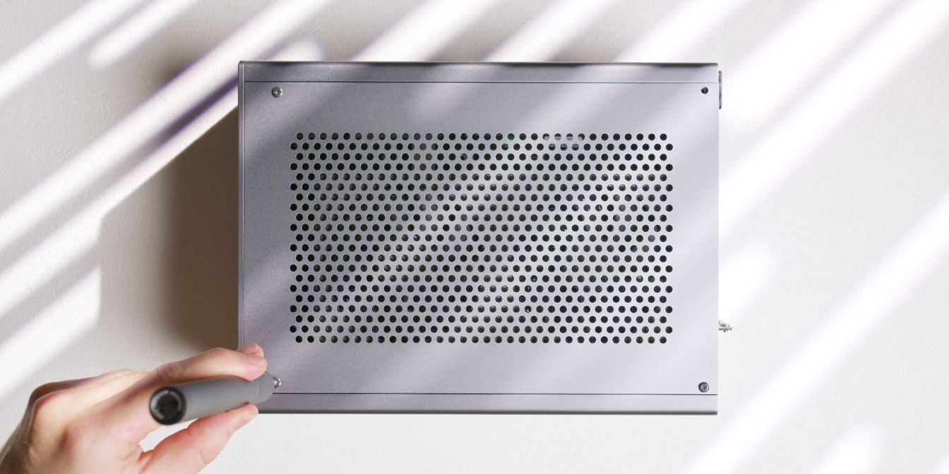
Case Feet
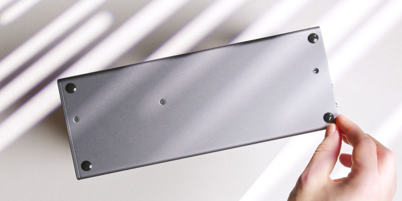
The Midori doesn’t include any case feet, but I decided to use these simple 10mm silicone bumpons placed on each corner of the panel.
And with that, we’re done with assembly 🎉
If you’ve found any mistakes, inaccuracies or missing information, please contact me.