Prep
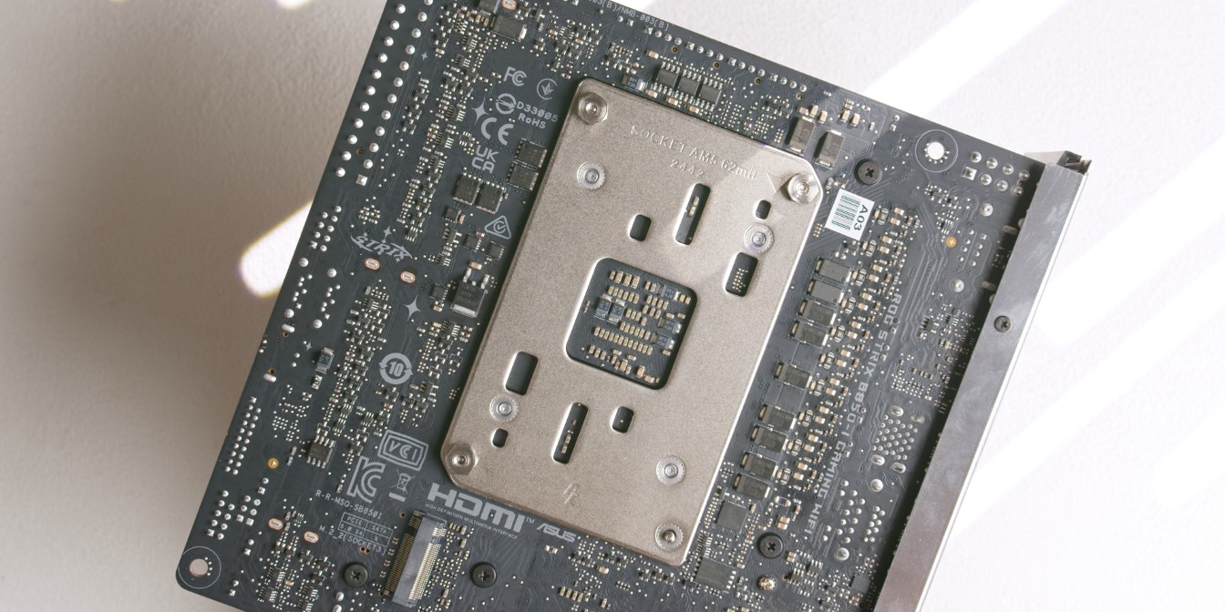
Motherboard
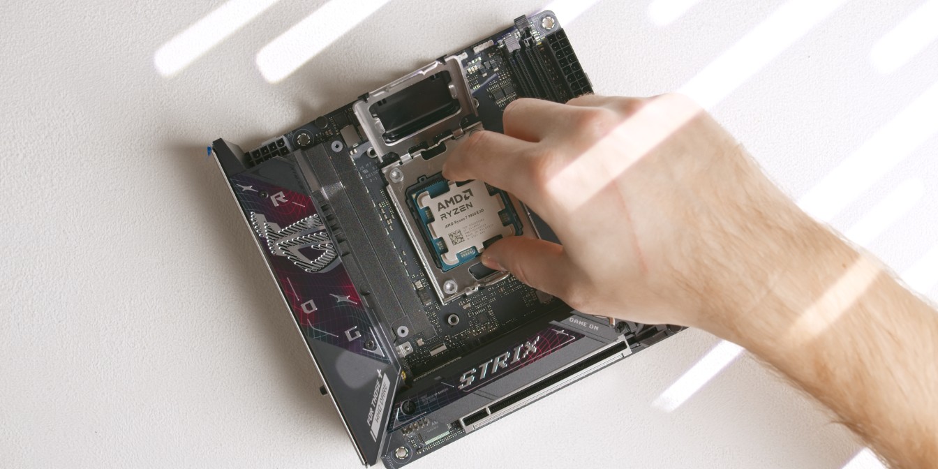
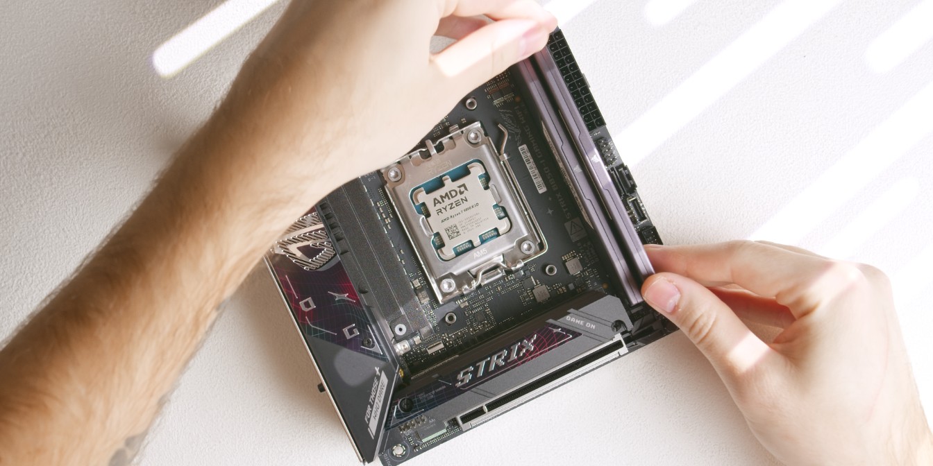
Let’s start by slotting in the 9800X3D CPU into the ASUS B850I motherboard.
For RAM I’m using a 6000Mhz CL30 64GB kit from Corsair, but 32GB is plenty, especially given the current prices of RAM kits.
I recommend looking for the cheapest 32GB Corsair, GSkill or TeamGroup kit around 6000Mhz and CL30-34.
Low profile RAM (35mm height or lower) is always good to have for SFF builds, but not required for this particular build.
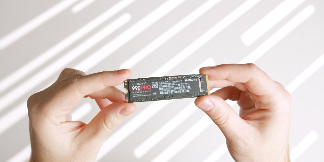
Storage: A single 4TB Samsung 990 Pro drive.
Gen5 drives like the 9100 Pro offer no real world advantages for regular desktop use or gaming, so the price premium is generally not worth it.
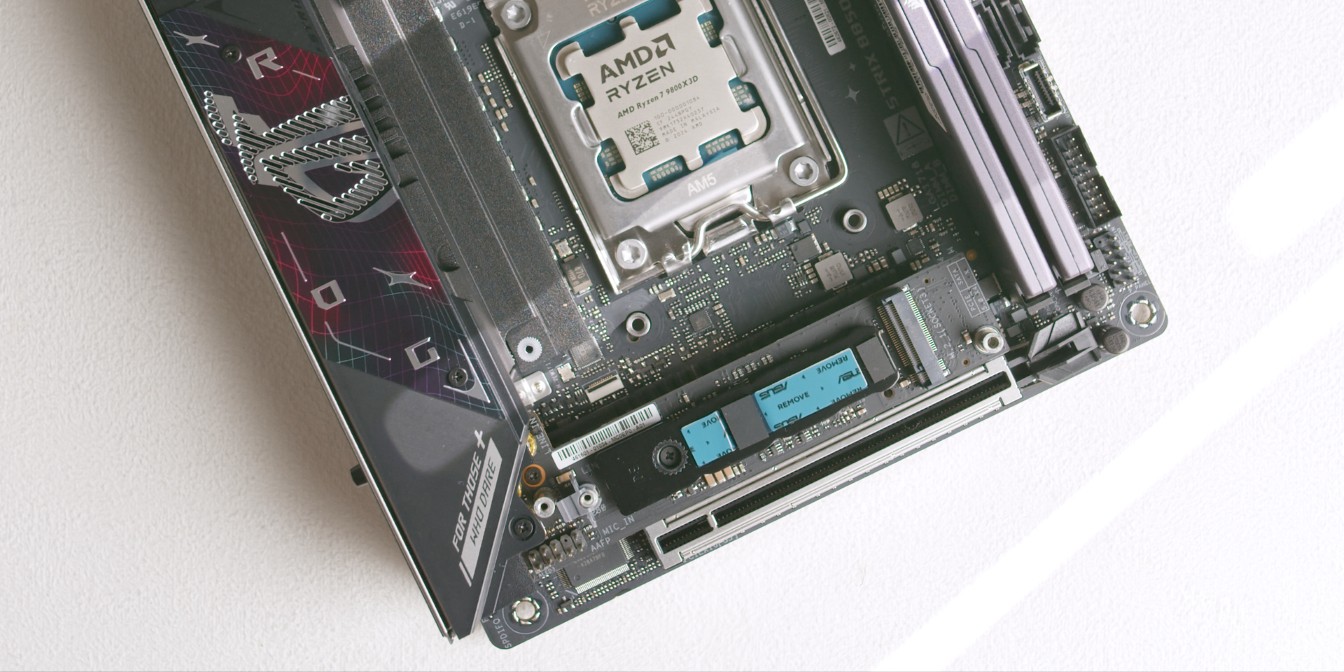
Customize this as per your needs, but keep in mind that you only get one drive. The B850I does feature an additional backside M.2 slot, but I generally don’t recommend using it in sandwich-style cases.
Since the 990 Pro is a single sided drive, peel off the protective plastic layer off from the pre-applied thermal pad on the top heatsink piece and leave the bottom one as is.
CPU Cooler
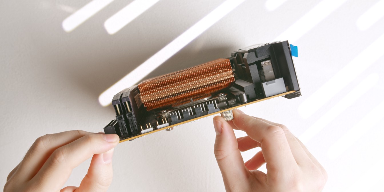
We will be using optional offset brackets from DingKey Designs to squeeze every ounce of performance out of the Thermalright AXP90-X47 Full Copper cooler.
They work by offsetting the cooler downwards so that the center of the coldplate sits directly over the hottest part of the CPU. See this video from Noctua explaining why this works on AM5 CPUs.
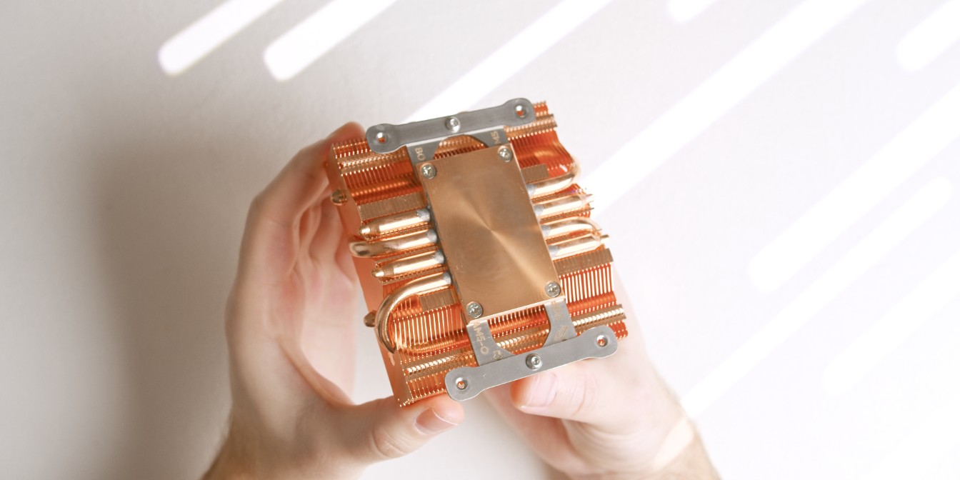
Use the original mounting screws to secure the two brackets to the cooler. Bracket orientation doesn’t matter for now, but make a mental note that one of the brackets is longer (marked with “TOP”).

The AXP90 X47 Full Copper comes with two sets of mounting screws, either will work for this build, but I recommend using the shorter ones as they won’t stick out on the other side of the motherboard.
Screw them into the brackets as shown.
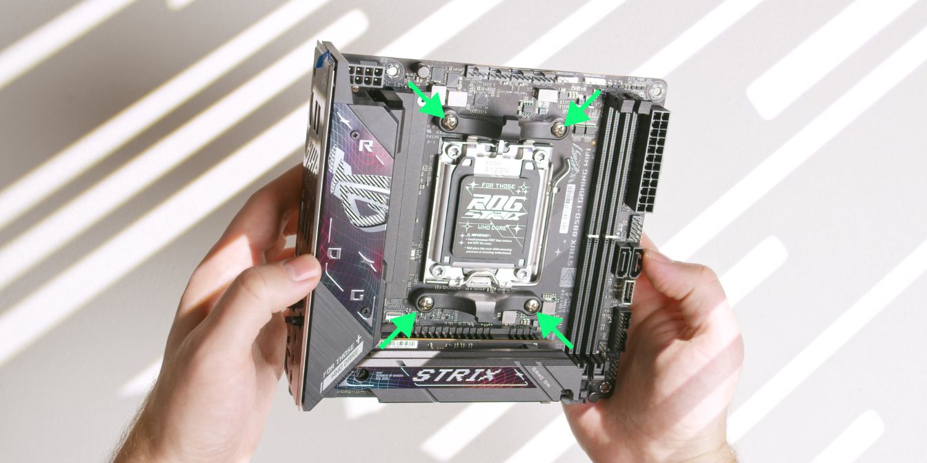
Remove the stock AM5 CPU mounting brackets by unscrewing the four Philips head screws. Place these in your motherboard box for safekeeping.
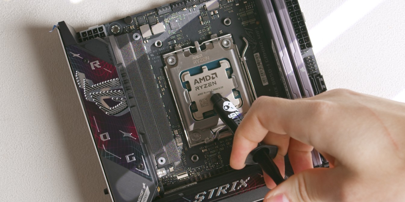
For consistency, I apply a pea sized drop of TG Duronaut (affiliate) on to the CPU. A more uniform method would be to use a cross patern but I find I’m less consistent with that method between applications.
Place the heatsink onto the CPU with the longer offset bracket towards the north (up) part of the motherboard.
Make sure that the screws are aligned with the AM5 backplate threaded posts and feed them through simultaneously, keeping the heatsink level.
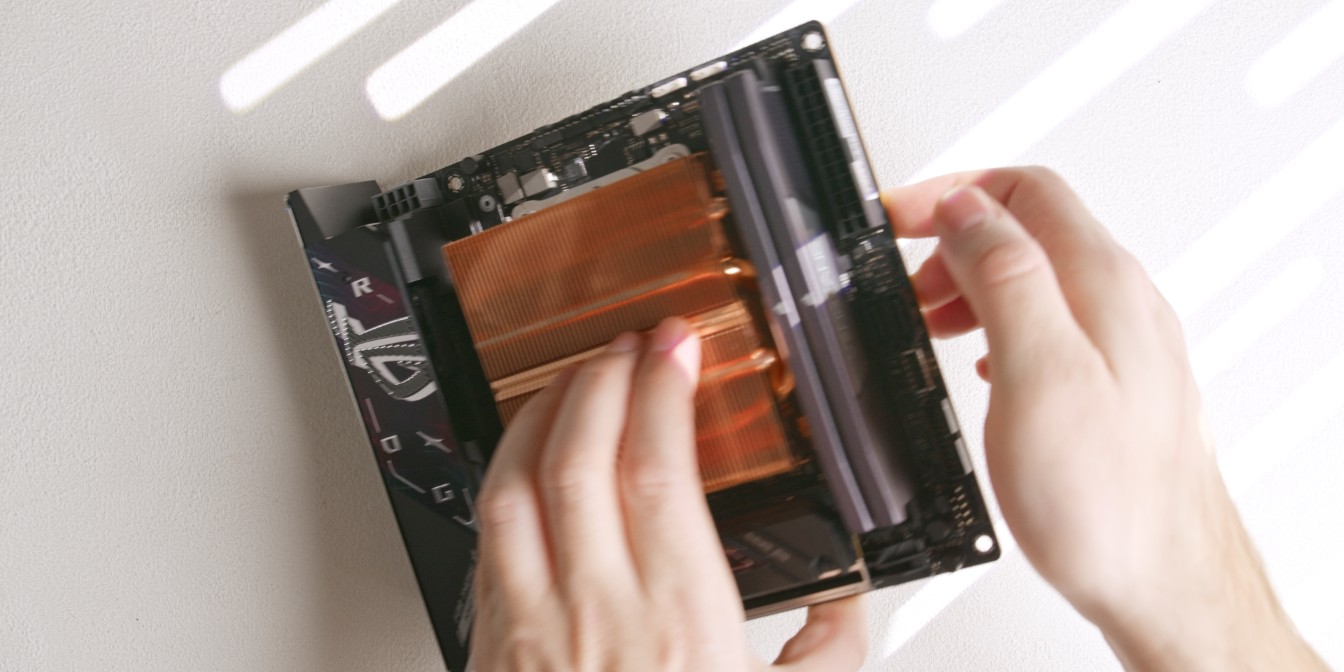
Flip the assembly around, holding the heatsink against the motherboard.
Hand tighten the included nuts onto the screws just enough so that the cooler won’t come off.
Continue tightening the nuts using the included thumb screw tool.
This will be easy to see on the motherboard’s north side, but very difficult on the opposite side as the leaf spring will be obstructed by the NVME heatsink.
I tend to go by feel here, going for an even tightness across all four nuts.
You can also look at how much each screw is protruding inside the nuts and have them all sit at about the same depth, although keep in mind that screw length may vary.
CPU Fan
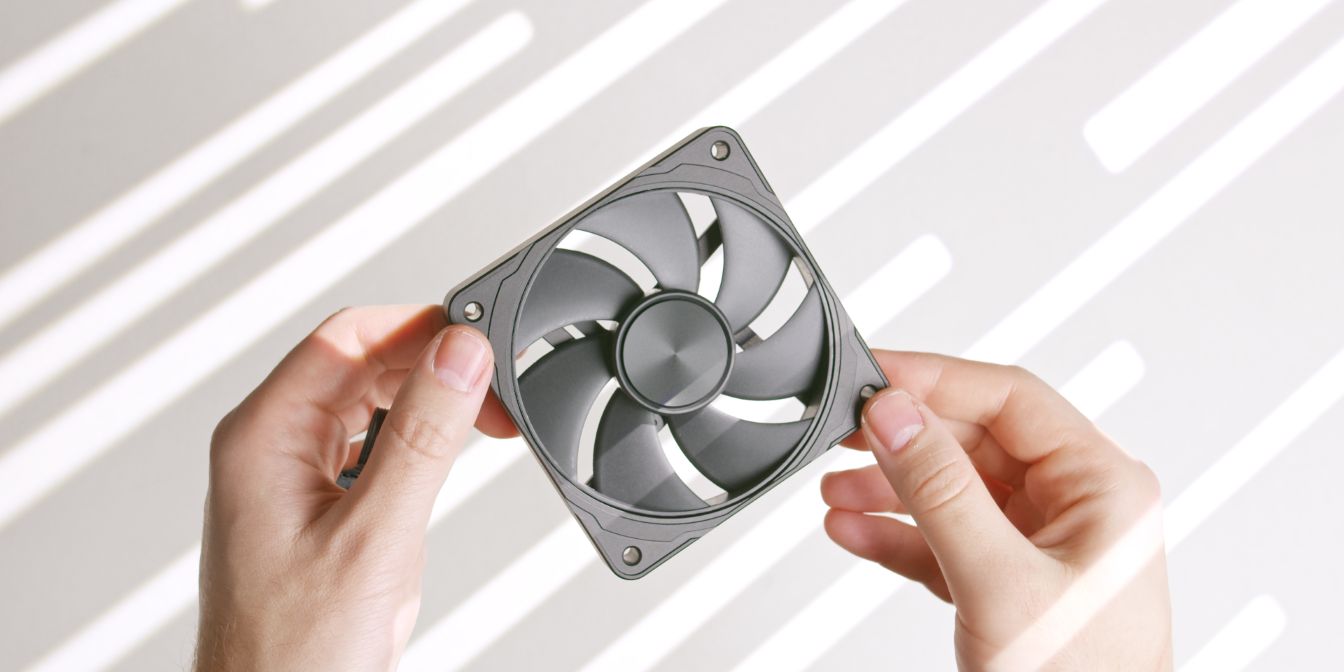
Instead of the included stock fan that comes with the Thermalright AXP90-X47 Full Copper we’ll be swapping to this Nidec 4070 fan housed in a metal CNC frame.
In my noise-normalized testing, the 4070 CNC fan slightly outperforms the Noctua NF A9x14, but not to the level that it would make a significant difference to thermals.
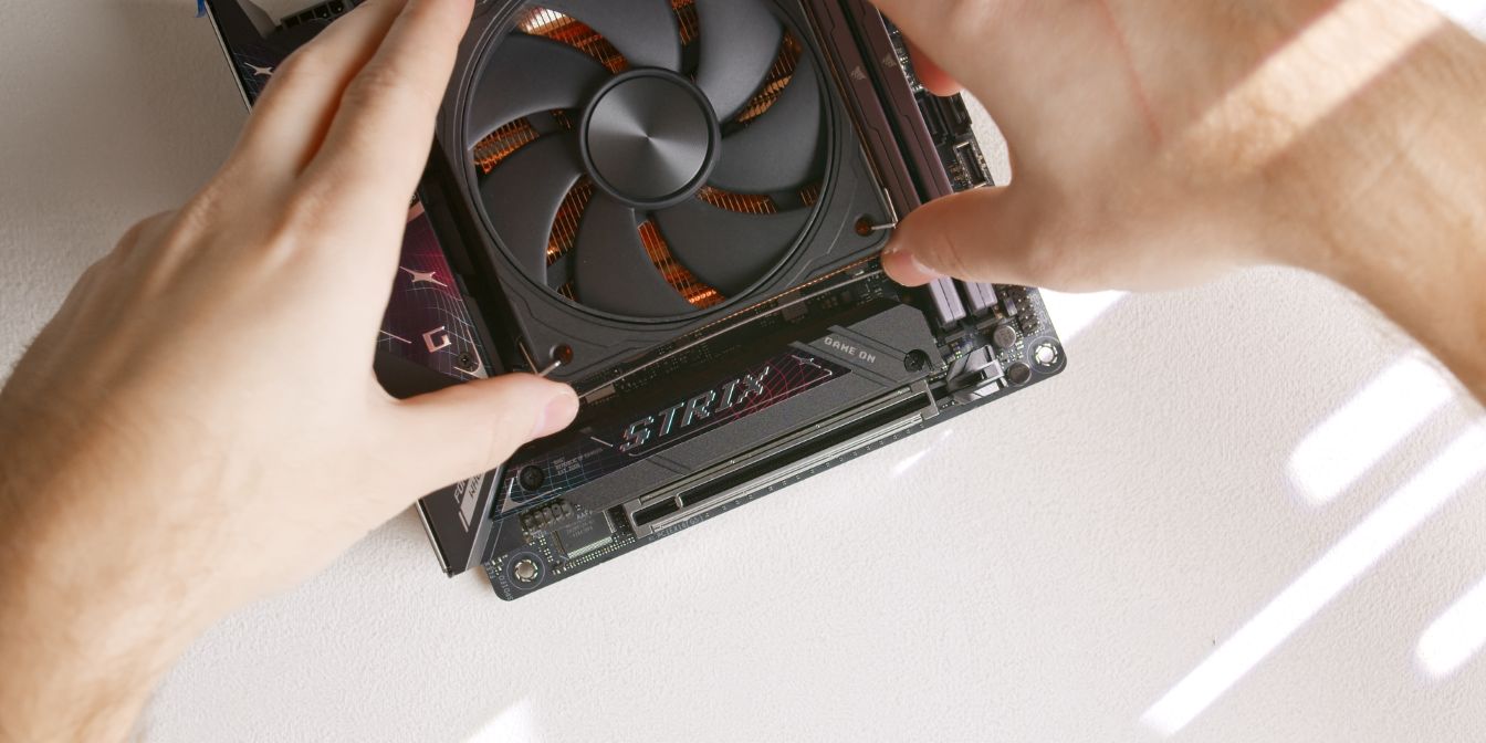
The stock AXP90 fan clips can be used for securing the 4070 CNC fan, but more force is required because the fan is slightly larger. Don’t be afraid to bend the fan clips.
Travel Kit
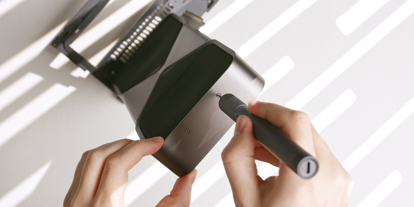
The Travel Kit is an official FormD T1 accessory that fully integrates the 5080 and 5090 Founders Edition cards into the T1. It comes with an anti-sag bracket and a custom rear I/O plate.
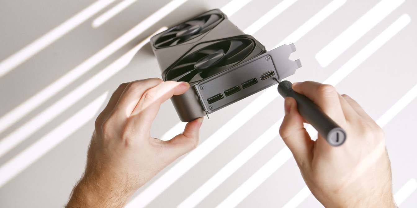
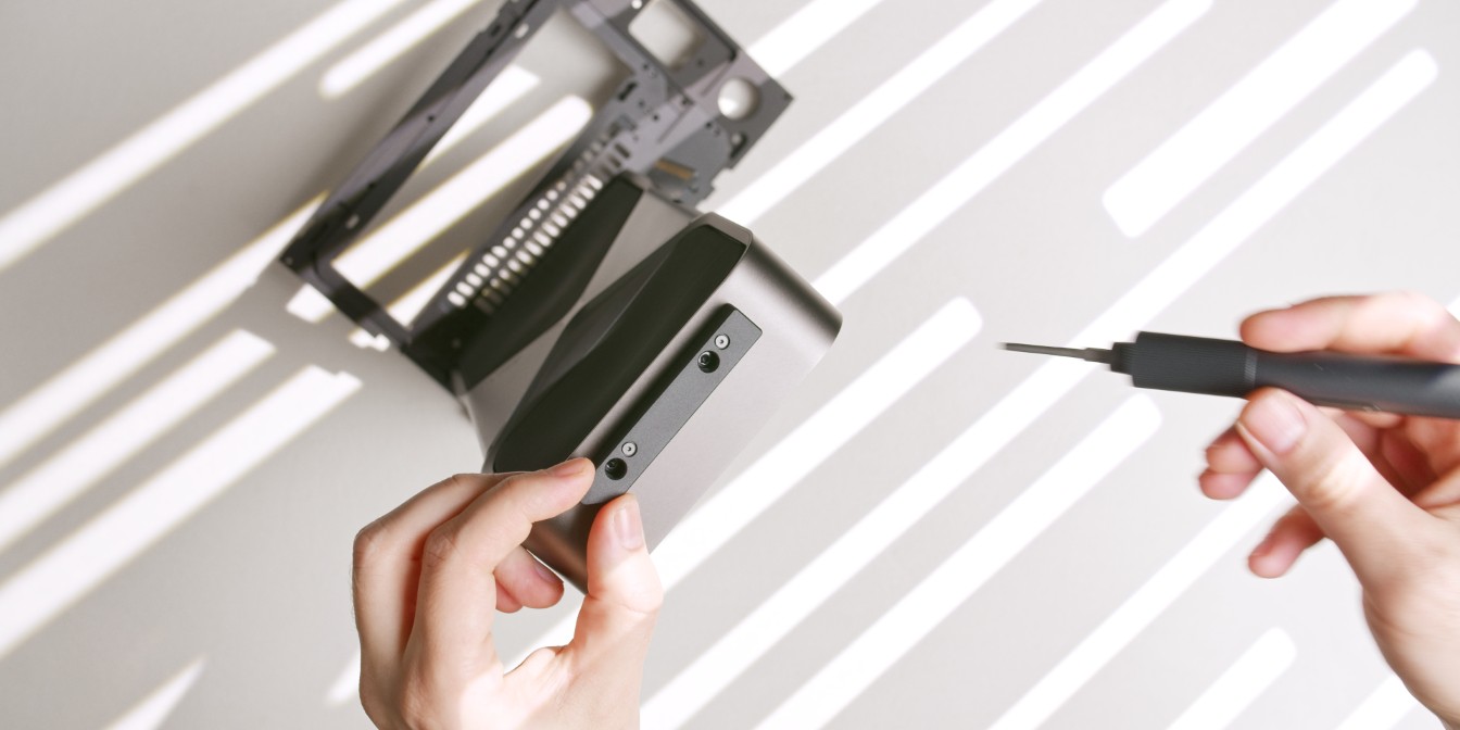
Start by removing the four Torx head screws holding the stock I/O plate.
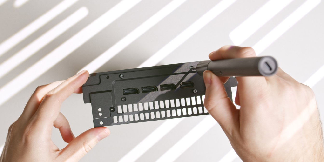
Use the same screws to install the travel kit I/O bracket.
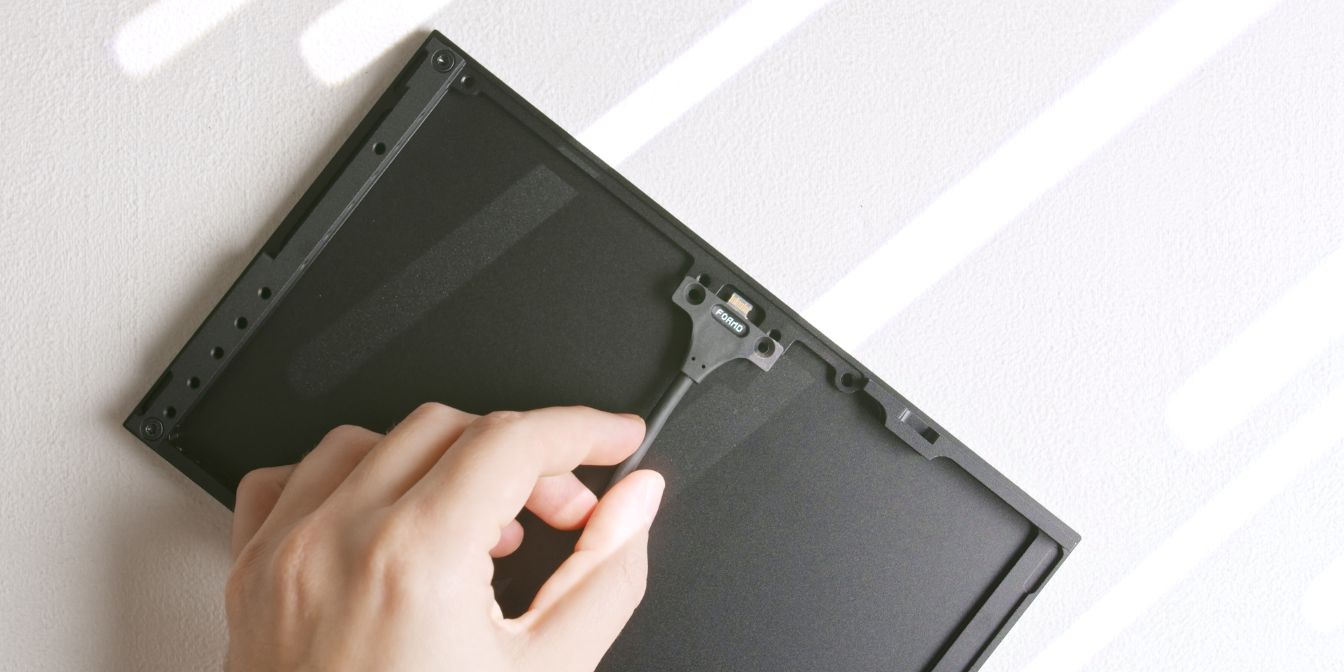
As we will be adding a one slot offset between the motherboard and the GPU, leave the additional gap filler piece attached as shown.
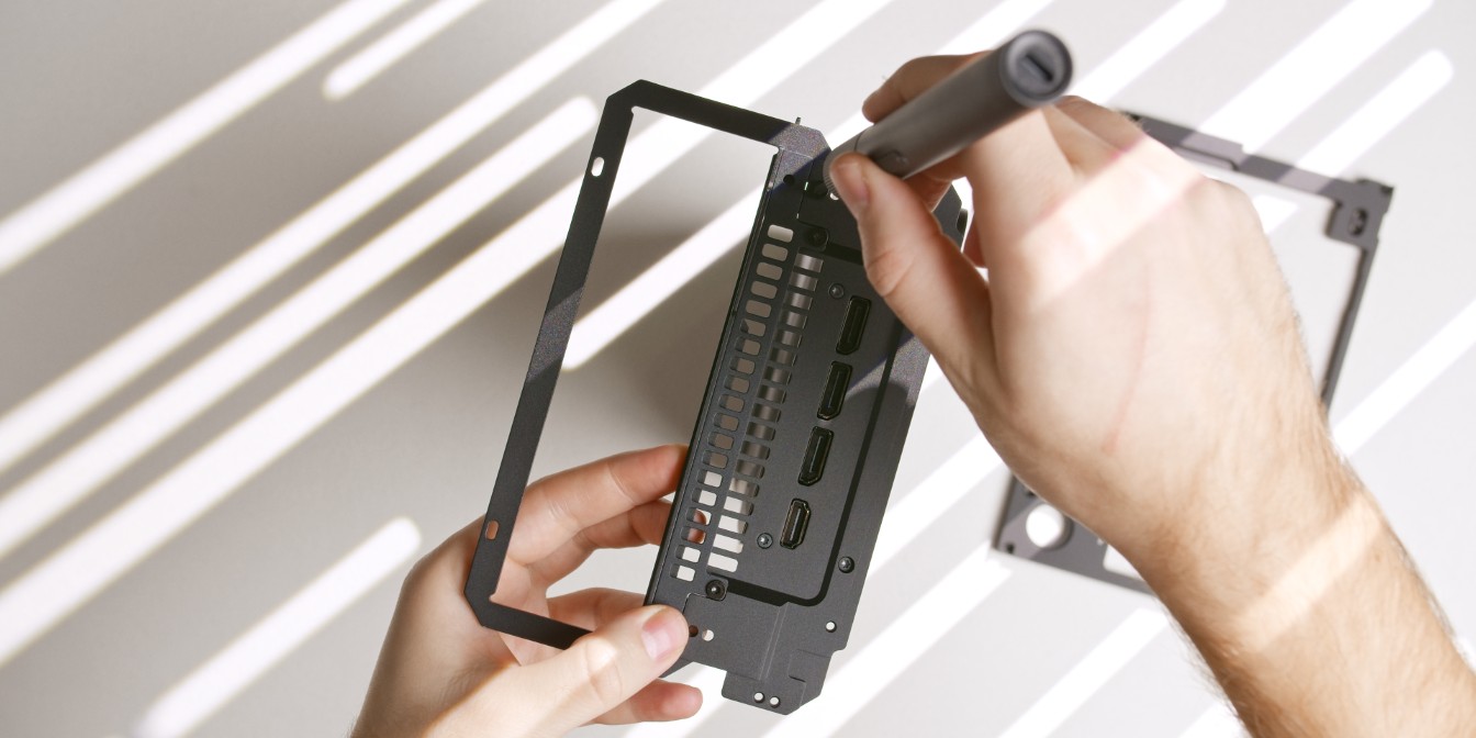
Add the rear panel insert and secure it to the travel kit bracket as shown.
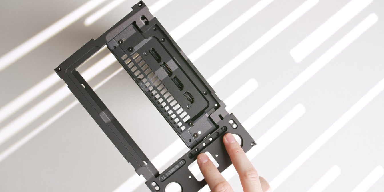
Place the T1 rear panel over the rear panel insert, align it as shown, and secure it with two screws in holes 2/6 and 6/6.
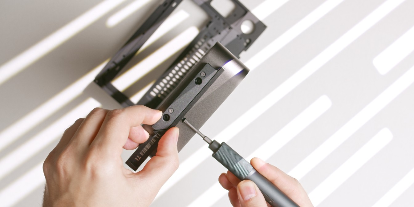
Next, remove the two small Torx T8 screws located on the opposite end of the GPU.
Secure the anti-sag mount onto the GPU with two screws.
The anti-sag mount should be oriented with the slanted corner towards the side facing opposite of the PCIe connector.
Finally secure the anti-sag bracket onto the GPU mount piece.
It’s already starting to look like we’re assembling the case, and that’s because we’ll be essentially be building the T1 around the travel-kitted GPU.
Type-C Cable
If you purchased the T1 essentials pack, secure the USB Type-C cable to the front panel.
Choose your preferred side of the front panel depending on the positioning of the T1 on your desk. I use the right side of the front panel (GPU side).
The power button cable can be added later, but it’s critical to add the Type-C cable now since it will be blocked by the GPU during later steps.