Assembly
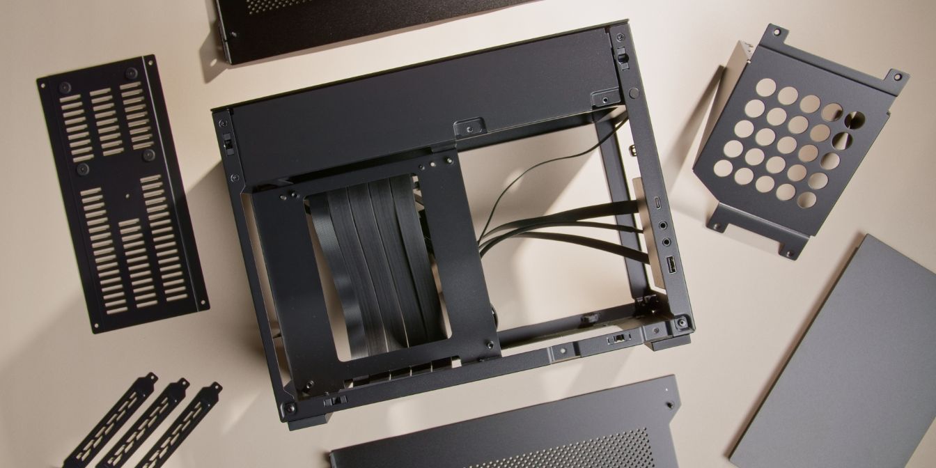
This guide assumes that you’ve removed all the case panels in preparation for assembly.
The guide also assumes that CPU, RAM and Storage were already slotted into to the motherboard.
GPU Riser
We will be adding a one slot offset to the GPU by using the two included 0.8 inch standoffs.
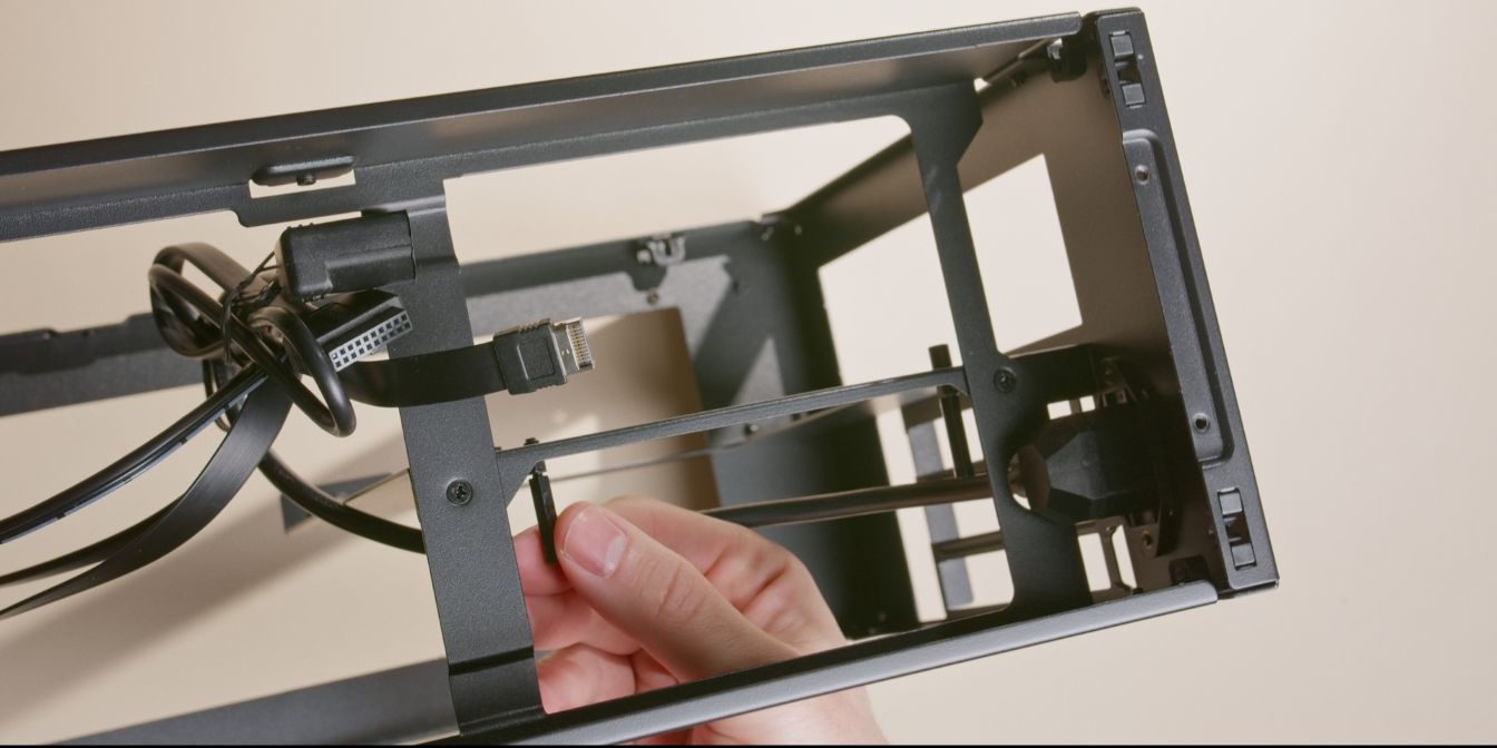
First, remove the stock riser by undoing the two screws holding it to the case motherboard tray.
Screw the two standoffs onto the riser mounting posts. Finger tight is fine but there is a thumb screw tool included in the accessory box should you need it.
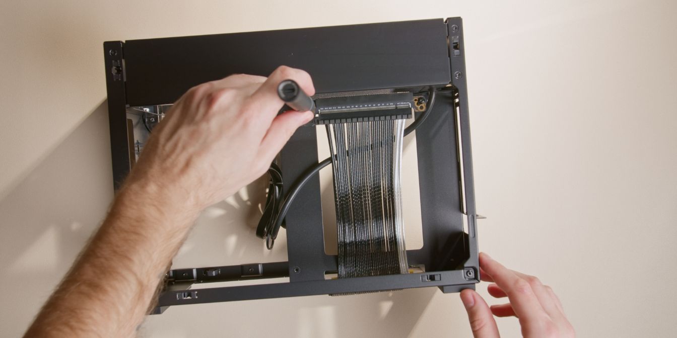
Secure the riser cable onto the standoffs using the original screws.
I replaced the stock Gen 4 riser that came with my case with the Gen 5 Monstronic SS200 for the FormD T1.
Newer batches of the A4-H2O have been updated to include a Gen 5 riser, so you shouldn’t need to swap it.
It’s also perfectly OK to use a Gen 4 riser with a 5080 or slower GPU, as long as you remember to manually set the PCIe link speed to Gen 4 in the motherboard BIOS.
Motherboard
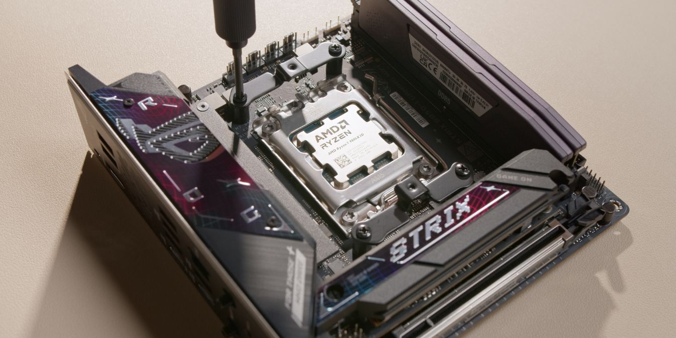
Prep the motherboard by removing the stock AM5 CPU mounting brackets and replacing them with the standoffs and brackets included with the Silent Loop 3.
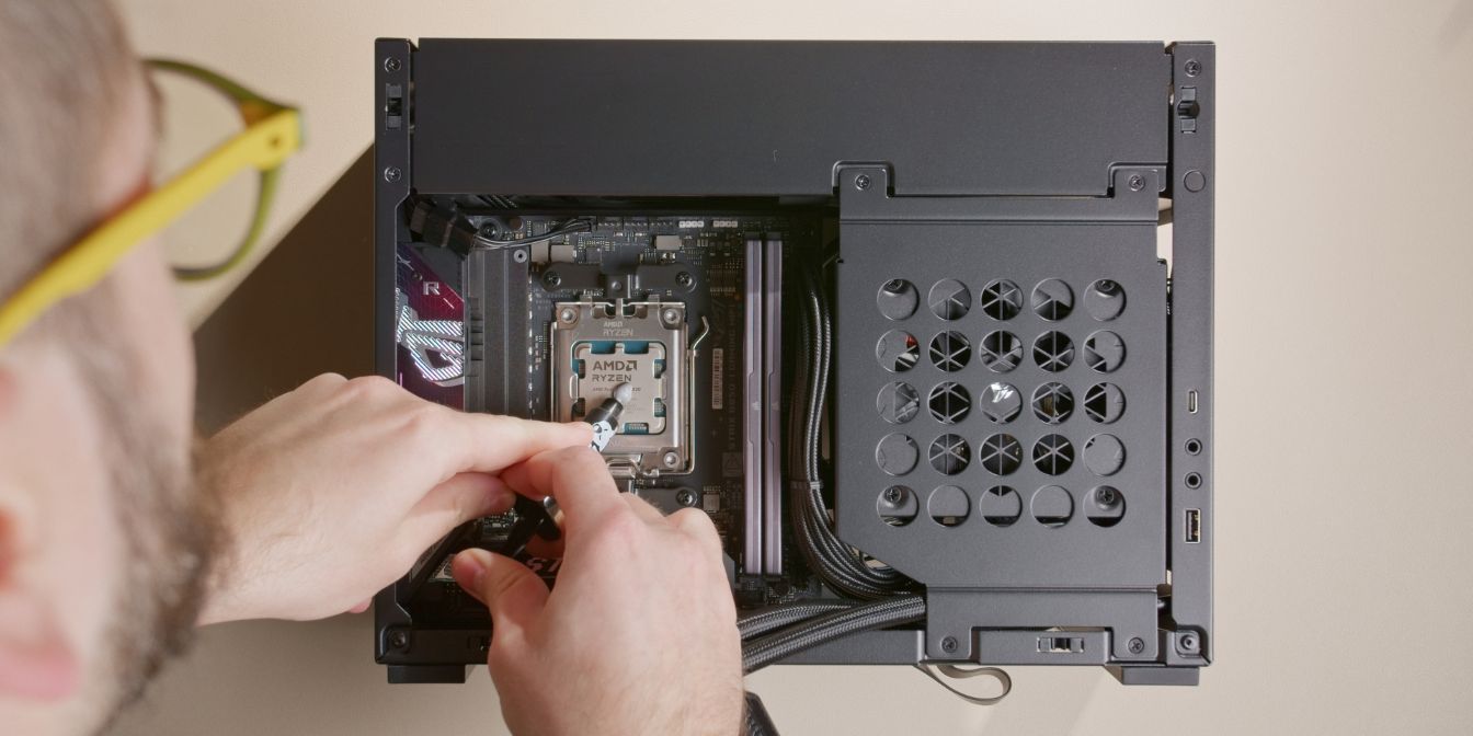
Place the motherboard onto the tray and secure it with the four included M3 motherboard screws.
The bottom left screw is difficult to get to. Try setting it in place with tweezers (or your fingers, if slender enough), then use a thin screwdriver to tighten it.
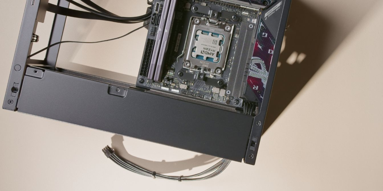
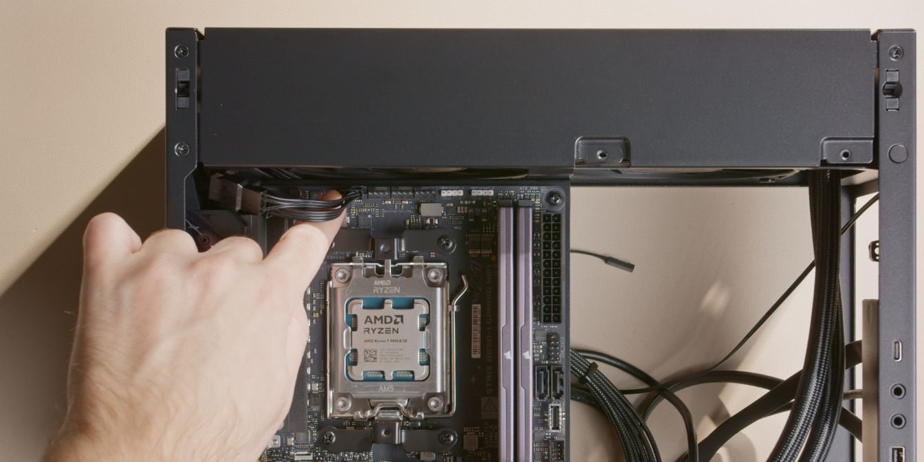
Connect the 8 pin CPU cable to the motherboard and pre-route it through the opening in the top section.
The cable should be routed behind the motherboard, sitting in between the motherboard tray and riser cable.
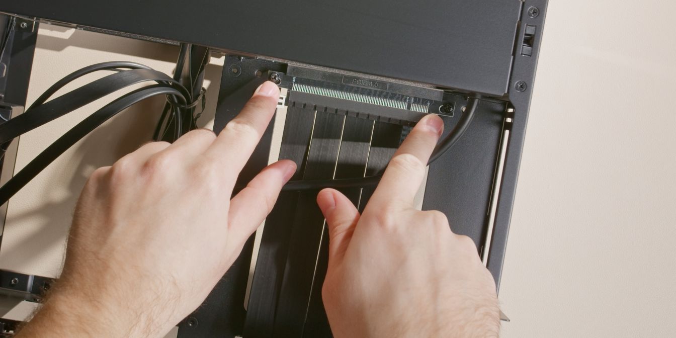
Slot in the PCIe riser into the motherboard, listening for the audible click of the retention latch.
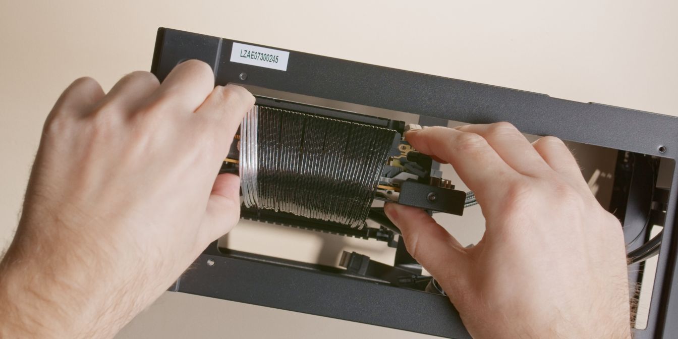
AIO Cooler
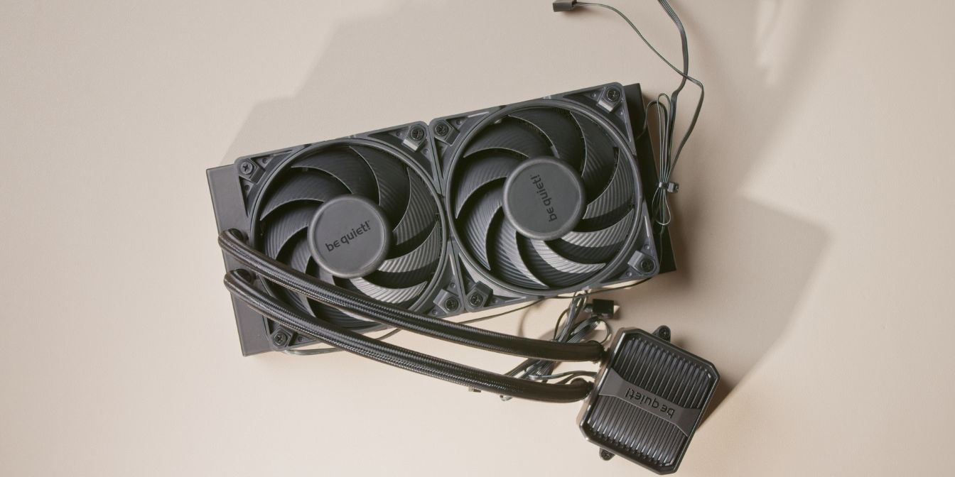
Let’s prep the Silent Loop 3 AIO for installation.
Secure the two fans onto the radiator with the long screws included in the accessory box.
Fans should be placed in the “push” configuration as seen in the image above.
Included in the accessory box of the Silent Loop 3 you will find a 4 pin PWM fan splitter cable, connect it to the ends of the fan cables.
Cable management tips:
- Position fan #1 with the cable towards the radiator ports
- Position fan #2 with the cable towards the opposite side
- Run the cable from the fan closest to the tubes along the sides of both fans
- Use a single zip-tie to tie the two cables together as shown.
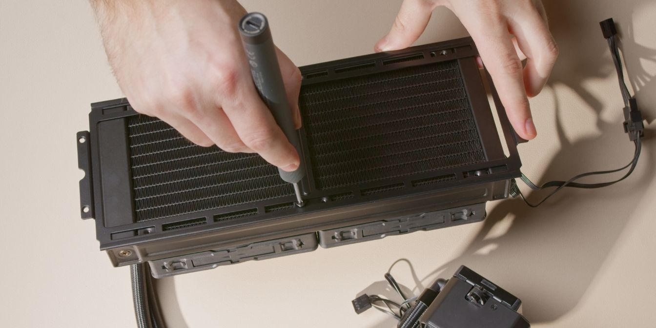
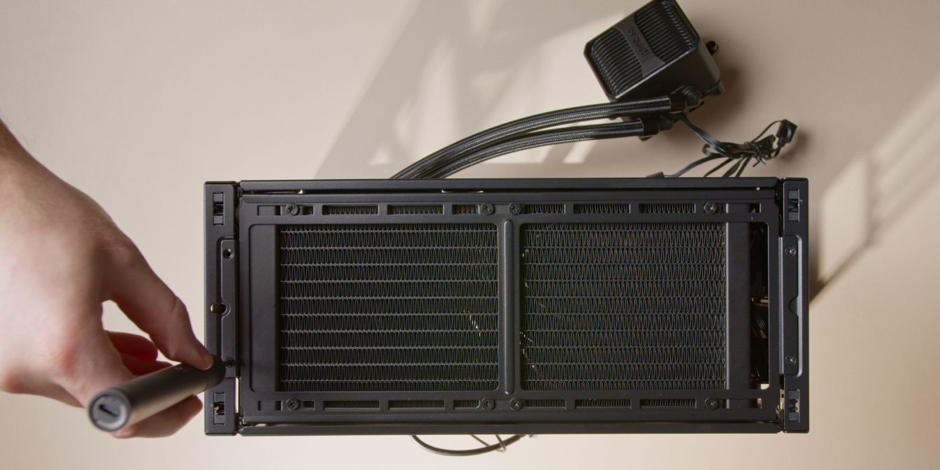
Flip the assembly over and secure the A4-H2O radiator bracket with 8 of the short screws included in the accessory box of the Silent Loop 3.
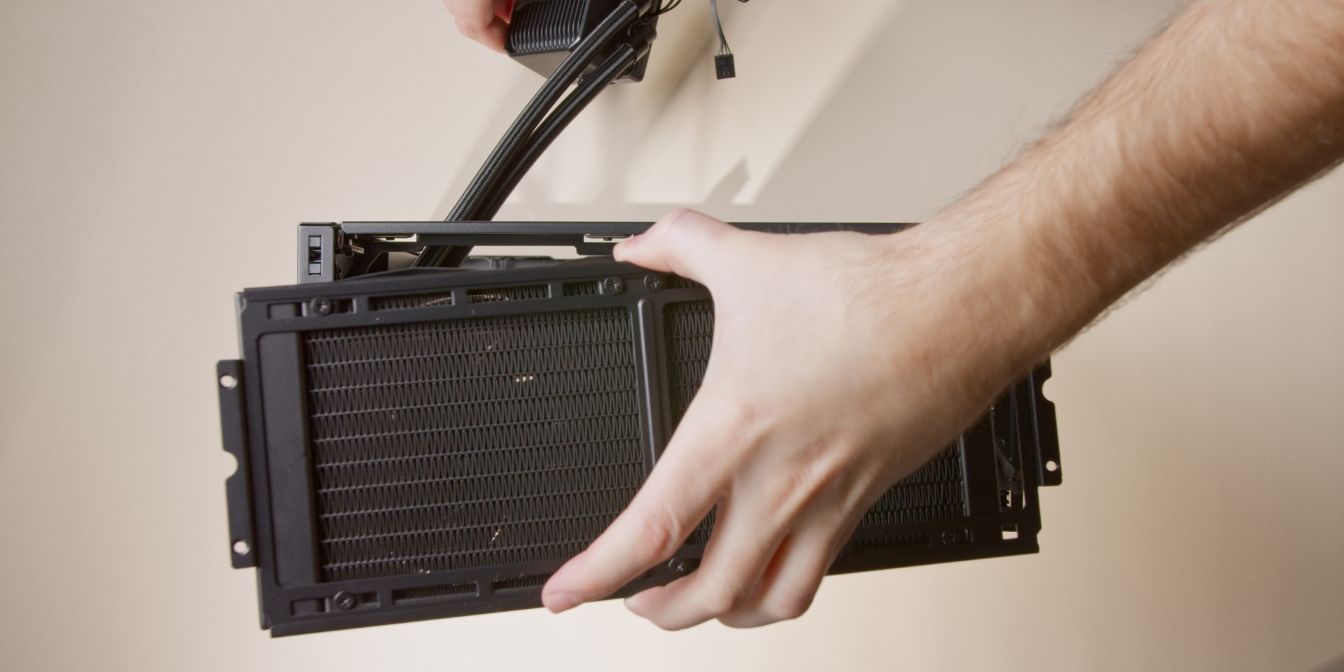
Place the AIO assembly into the case through the top opening and feed the 4pin fan splitter cable through the same opening used earlier for routing the CPU 8 pin cable.
As you lower the AIO into the case, make sure the cable managed fan wires don’t get caught.
Once the AIO bracket is seated, check if all the cables are where they should be.
Secure the AIO bracket with the original screws.
If you left the radiator screws slightly loose, you can now adjust the positioning of the AIO. I recommend positioning it slightly closer to the front panel to make tube routing easier. Don’t forget to tighten all 8 screws.
You can now also snap the top panel back onto the case, as we will no longer need topside access.
If you did everything during the previous steps correctly you should have just enough slack in the fan splitter cable to connect it to the CPU_FAN header on the motherboard.
Optional step
To keep the AIO cooler block from getting in the way I recommend temporarily mounting it onto the CPU.
Leave the plastic film on the coldplate in place and tighten the cooler only a few turns.
Don’t worry, I’ll remind you later 👀
PSU
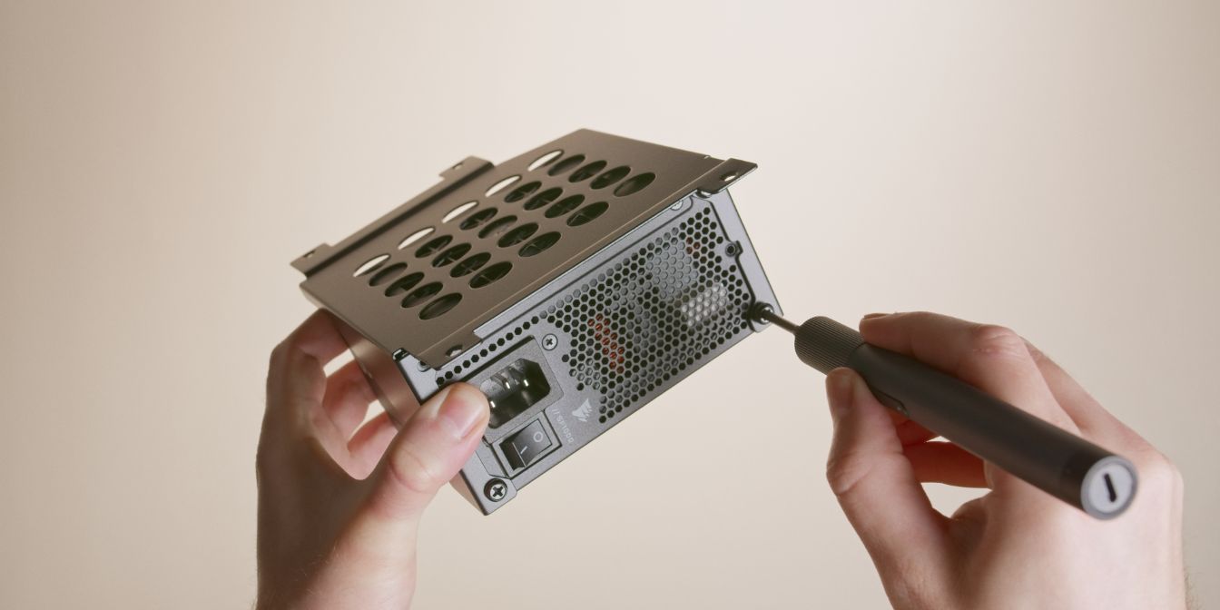
Secure the power supply to the PSU cage using 4 of the power supply screws included in the accessory bag of the A4-H2O.
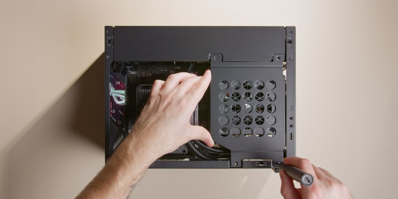
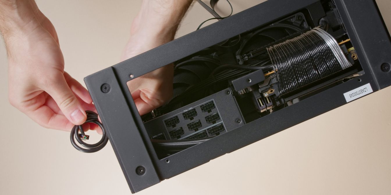
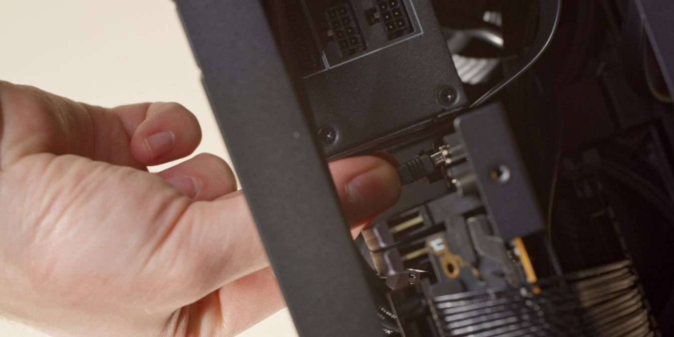
Bring the PSU in position and connect the internal power cable to the power inlet of the PSU.
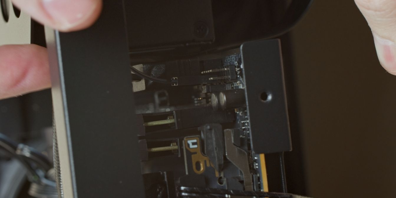
Place the assembly into the correct position and secure it with the original screws.
You will need to hold the PSU cage aligned by pushing it slightly against the AIO tubes.
Cables
The A4-H2O has a lot of front panel cables we need to manage.
Personally, I don’t use on-board audio on any of my PC builds, so I coiled up the front panel audio jack cable and hid it out of sight in the bottom part of the case (below the PSU, towards the front panel)
Connect both the regular USB and the USB Type-E cables to the appropriate motherboard connectors.
Connect the power button cable to the appropriate pins on the F_PANEL header of the motherboard.
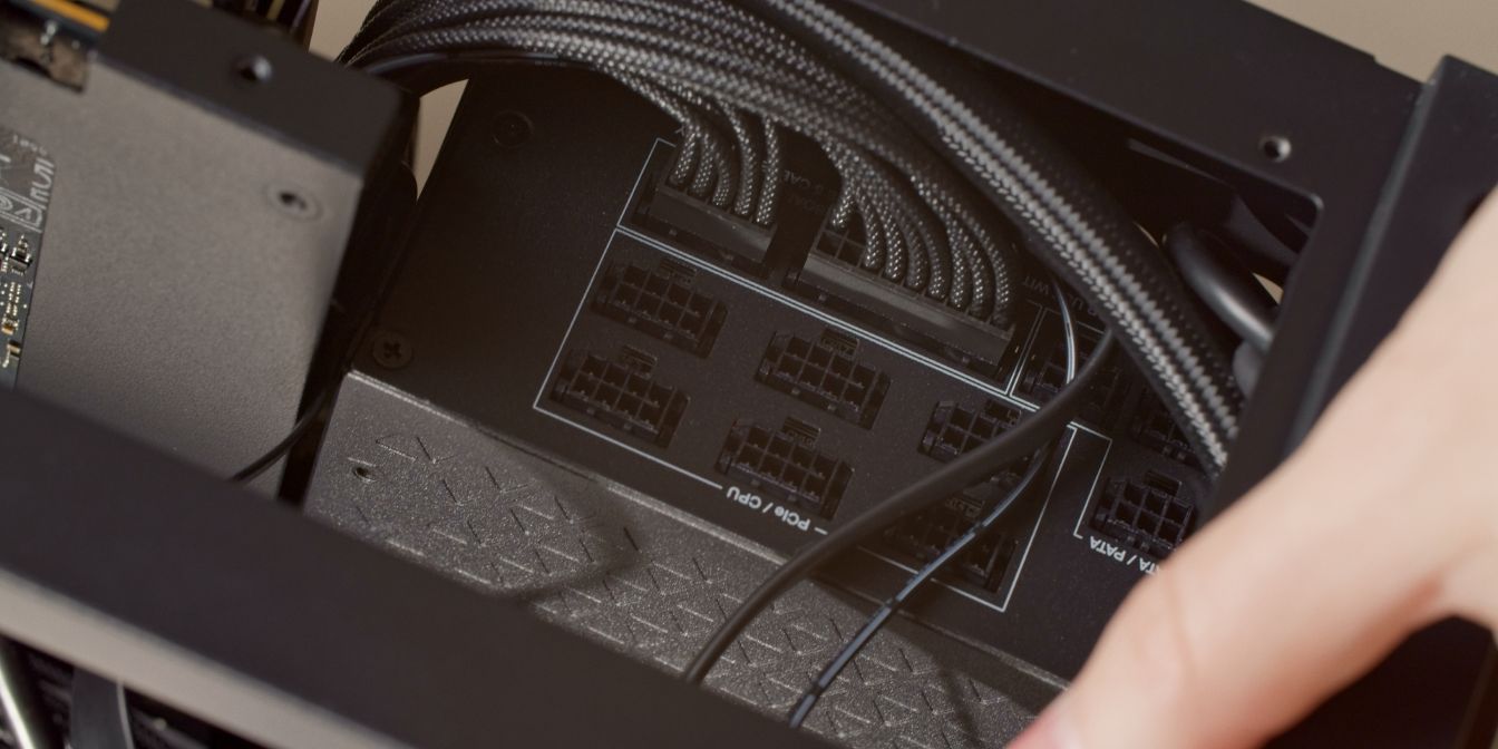
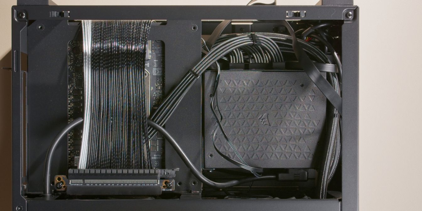
Connect the motherboard 24 pin PSU cable to the motherboard and the PSU.
Note the routing of the two front panel USB cables as well the power button cable. The motherboard PSU connectors will hold these cables against the PSU cage.
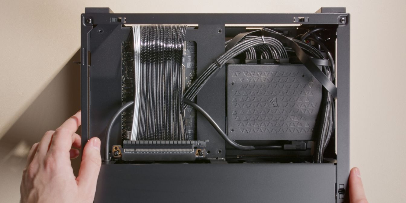
Connect the 8 pin CPU cable routed during the Motherboard assembly step to the PSU.
Try to manage the front panel cables as best you can so that they are more or less contained to the area around the PSU. These flat cables are hard to manage neatly, so don’t expect perfection here.
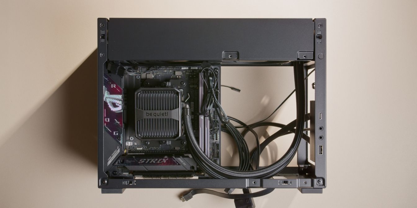
AIO Block
With most of the cables sorted, you can now finalize the AIO CPU block installation.
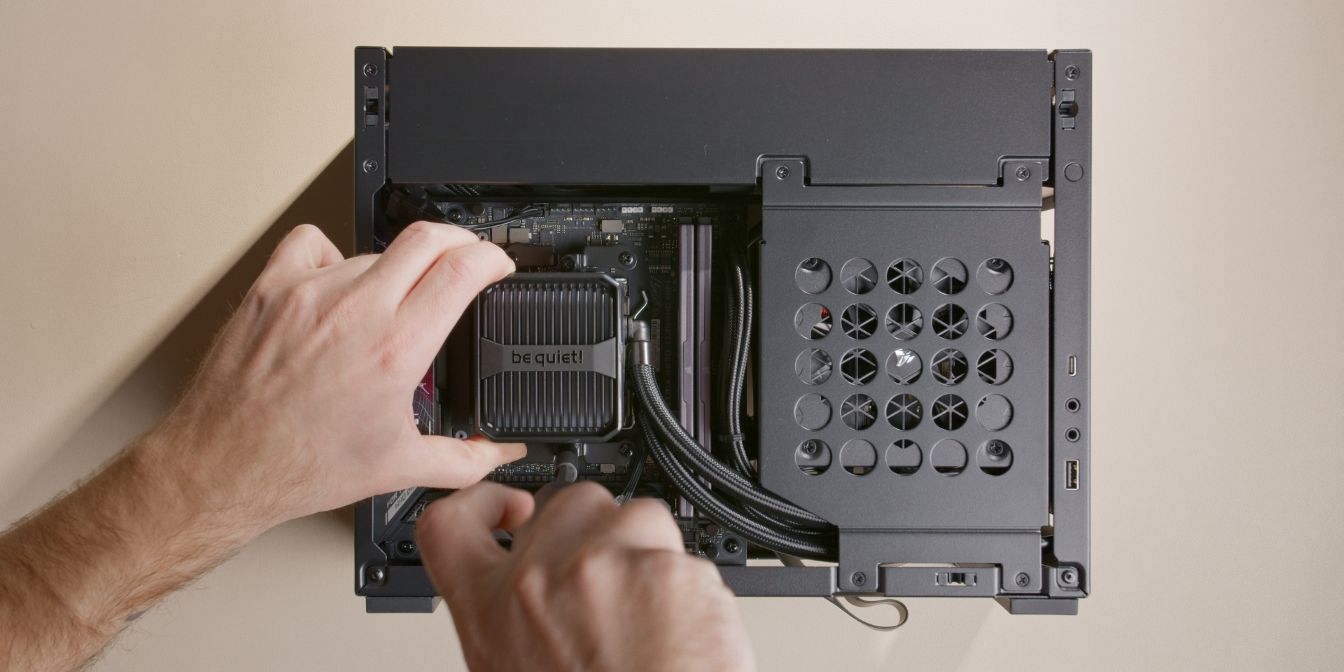
Align the Silent Loop 3 CPU cooler block with the mounting brackets.
Tighten the cooler block in an alternating pattern until you reach the hard stops of the captive screws.
Pump Cables
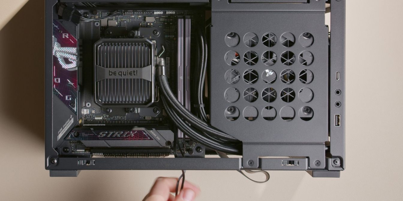
The Silent Loop 3 comes with two excessively long cables coming out of the cooling block: the 4 pin pump PWM cable, and an ARGB cable.
I didn’t want to simply stuff them somewhere so I went the extra mile and routed them in a way that they are no longer visible.
First, route them in between the PCIe slot and RAM slots, having them exit towards the bottom of the case.
Flip the case over (with the bottom panel away from you) and route the cables over the PSU backside, having them exit on the opposite side, towards the “top” of the motherboard.
Tuck the excess cables away between the motherboard and the motherboard tray. Alternatively, you could use zip ties to bundle them neatly.
Pull enough excess of the two cables so that they reach the motherboard fan header area.
Make sure the cables clear the AIO fan blades.
Connect the 4 pin pump header to the AIO_PUMP motherboard header.
Connect the ARGB header to the motherboard “ADD Gen 2” ARGB 5V header.
Logo Removal
![]()
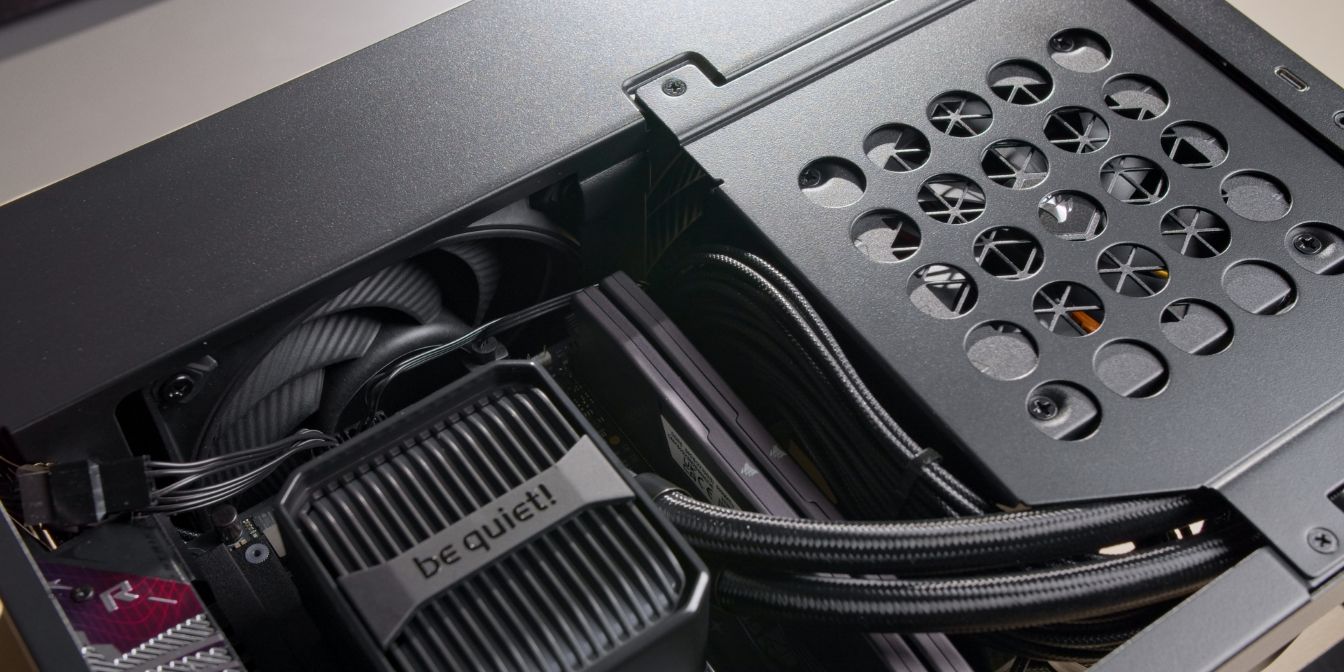
Optional Step
The Silent Loop 3 pump block may touch the A4-H2O’s side panel.
We can avoid this with a simple non-destructive mod by removing the “be quiet!” logo.
Use a plastic prying tool to lift up the plastic piece. The logo is held on with two clips on each side.
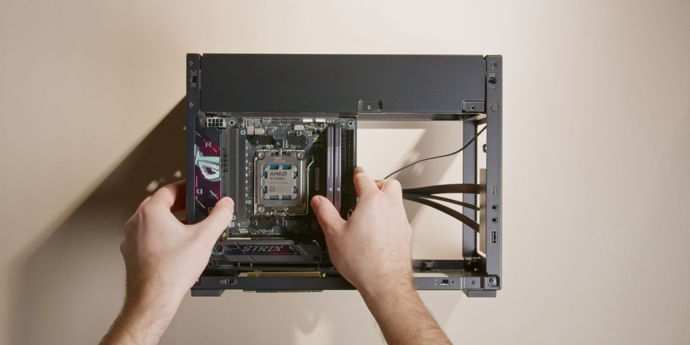
GPU
First, remove two (or all three) of the rear PCIe slot covers.
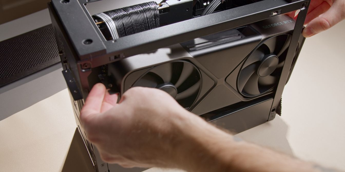
Get the GPU into position by inserting it through the front side opening.
Position the GPU carefully, aligning the PCIe connector with the riser slot.
After making sure the card is aligned correctly and the rear bracket is slotted into the retention clips located on the rear panel, push the card downwards into the riser.
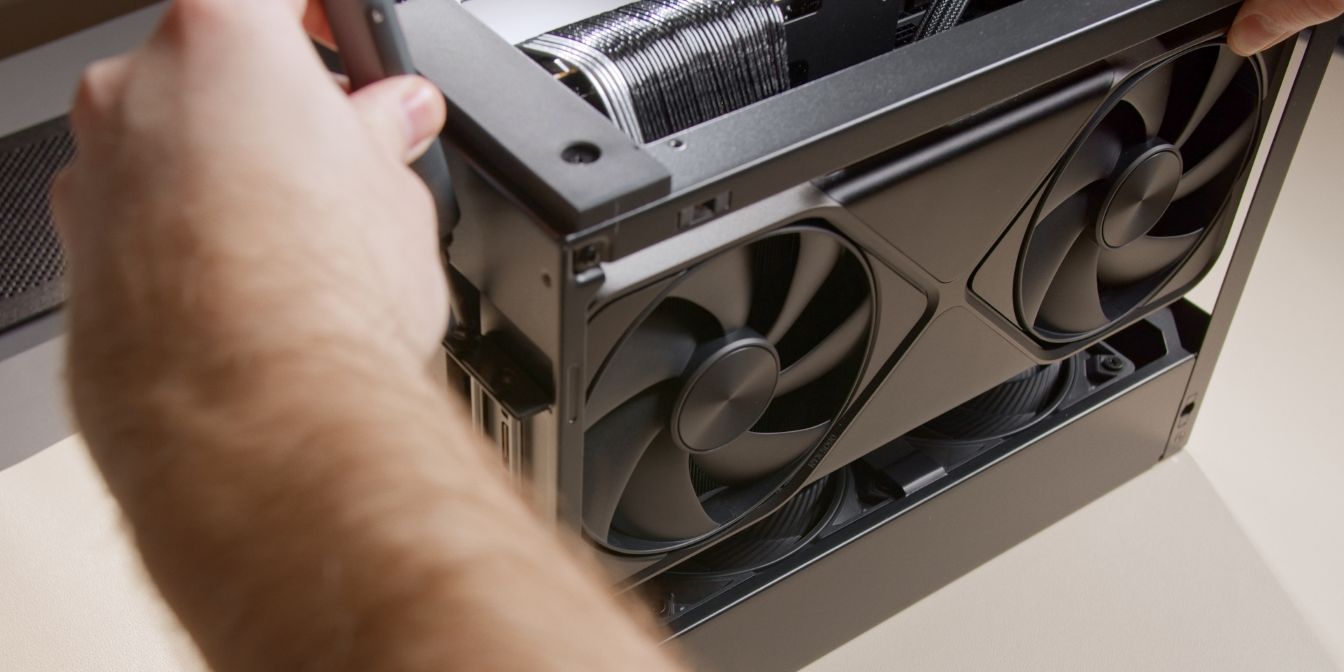
Secure the GPU rear bracket with two of the original rear PCIe cover screws.
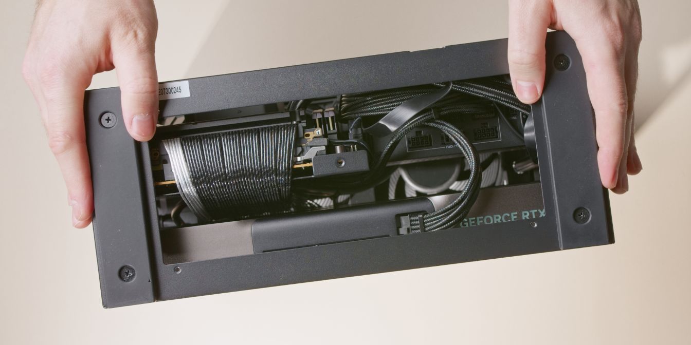
Connect the 12V-2x6 cable to the PSU and GPU, making sure it is fully seated listening for the audible “click” of the connector retention latch
Double, triple, quadruple check that the GPU connector sits perfectly straight and with enough slack.
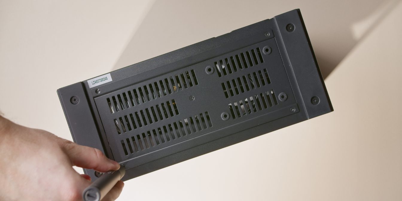
Screw the bottom panel back onto the case, using the original screws.
Side Panels
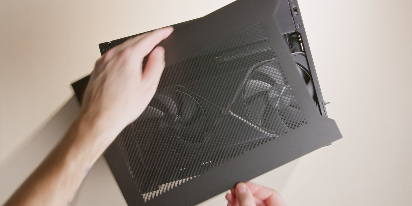
Place the front panel and side panels back onto the case.
Note that the side panels are not interchangeable and will only fit on their original side.
Secure the side panels with four thumb screws.
And with that, we’re done with assembly 🎉
If you’ve found any mistakes, inaccuracies or missing information, please contact me.